|
Additional symbols in tolerance shape designation |
Scroll |
The designation of the tolerance of the shape and location of surfaces in the drawing and model may contain additional signs — designations of the intersecting and / or orienting plane (see GOST R 2.308-2023). To add a designation, specify it in the Mark group of elements on the Parameter panel.
 Intersecting plane — used if the tolerance relates to a surface element located in a certain plane, for example, the straightness tolerance of a line in a plane, the tolerance of a specified profile, etc.
In a drawing, the intersecting plane is the projection plane of the view on which the tolerance is indicated.
 Guiding plane — used to indicate the orientation of the tolerance field width relative to any element of the part in the case when the standardized element is the midline or midpoint, and the tolerance field is limited in width by two parallel planes.
In a drawing, the orientation of the planes limiting the tolerance field is determined by the direction of the connecting line of the tolerance frame.
The sign of the intersecting/orienting plane is a table similar to the tolerance table, with additional graphic symbols and is located to the right of it. In the first cell of the table, a symbol is entered that determines the location of the plane relative to the base, and in the second - the letter designation of the corresponding base
Symbols of the location of the intersecting plane relative to the base
Element |
Description |
|
|
Parallel |
The plane is parallel to the base plane. |
|
Perpendicular |
The plane is perpendicular to the base plane. |
|
Contains |
The plane contains a base element. |


Symbols of the location of the guiding plane relative to the base
Element |
Description |
|
|
Parallel |
The plane is parallel to the base plane. |
|
Perpendicular |
The plane is perpendicular to the base plane. |
|
Slanting |
The plane is at an angle to the base plane. |

A special symbol can be placed in a line next to the tolerance table only once.
To delete a symbol, use the Delete symbol command in the context menu of a table cell.
|
If the tolerance table contains merged/split cells, then an additional sign cannot be added to the shape tolerance designation. |

|
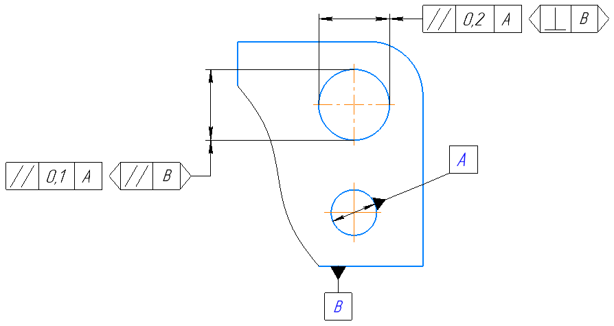
Example of indicating the guiding plane in the form tolerance designation