|
Editing Dimensions |
Scroll |
To edit the created dimensions, you can use various editing options available for objects in KOMPAS-3D system.
You can select a dimension using your mouse and modify its parameters and configuration as required or you can start the dimension editing process and use it to edit your dimension. For general information on editing objects using these methods, see the Editing objects. For notes on dimension modification, see below.
You can copy and move dimensions using your mouse or special commands. These actions work for dimensions in the same way as for other objects in a graphic document.
Moving and copying objects using the mouse
Commands to change the shape and position of objects
Changing dimensions without starting the editing process
You can select a dimension using your mouse and modify it as required by setting new parameter values on the Parameter Panel and/or moving the defining points of the dimension.
Each dimension has multiple defining points. The number and position of these points depend on the dimension type and dimension text placement method. See the figure below for examples of defining point positions for linear and angular dimensions.
Defining points can be moved for a dimension in the same way as for other objects in a graphic document. Details...
|
|
a) |
b) |
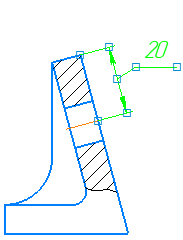
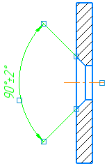
Display of defining points for selected dimensions:
a) linear, b) angular
While working in parametric mode, the value of the dimension in can be changed in special dialog. To call this dialog, double-click dimension text. Use it to modify the dimension value, the name of the variable, dimension tolerance, etc.
Changing dimensions in the editing process
You can start the editing process to change a dimension. The following actions are available in this process.
•Changing dimension parameters using elements in Parameter Panel.
Upon switching to the editing process, the command with which the dimension was created is started. Parameters are changed in the same way as they are set when setting the dimension.
•Configuring dimension text and changing the dimension value. Details...
|
If you want to edit only dimension text, double-click it. It will launch the dimension text editing mode. After you complete your work in this mode, dimension editing will be completed. |

•Editing dimension using defining points. Note the following about these actions.
Dimension’s defining points in the editing mode are different from the ones displayed when you simply select the dimension (without starting the editing process). The number and location of these points depend on the dimension type and dimension text placement method. See the figure below for examples of defining points for linear and angular dimensions in the editing mode.
|
|
a) |
b) |
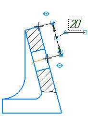
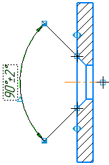
Display of dimension defining points in the editing mode:
a) linear, b) angular
Since defining points are used to perform different actions, they have a different shape.
•Points  allow altering the position of extension lines of the dimension and the position of the vertex of the angle for the angular dimension. If the dimension text is located on landing, the points of this type are displayed at the beginning of the leader and at the end of the landing. Use them to move the leader and rotate the landing.
•The points  allow to shift the dimension line. They can also be used to change the type of dimension arrows. To select the required arrow type, open the context menu on its end (where the point is displayed). You will see a list of all available arrow types.
•Point  can be used to move the dimension text when placed manually or the landing when placed on a landing. For radial and diameter dimensions, this point also rotates the dimension.
|
If the radial dimension is placed on the landing, you can add a new branch by double-clicking the point To delete a branch, select the point |

•The point  allows to change the angle of inclination of the extension lines.
|
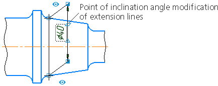
Point of inclination angle modification for dimension lines
In addition to defining points, an icon used to control display of an extension line is displayed next to the line in the editing mode:
• extension line is displayed,
• extension line is not displayed.
Click the icon to display/hide an extension line.
Exploding dimensions
You can explode a dimension into its constituent objects, if required: segments, arcs, texts, fills and hatches.
This is done using the Destroy  command in the Edit menu or the context menu of the selected size.