|
Leader |
Scroll |
To create an arbitrary leader, use the Leader  command.

Step-by-step instructions
1.In the graphic area, specify the object to which the first branch of the leader line is pointing. As the object being designated, you can use any object of the model – a face, a plane, a vertex, an axis, an edge, a dimension, a designation, etc. The name of the selected object will appear in the Objects field on the Parameters Panel.
In the graphic area, a designation phantom is displayed. The final point of the first branch coincides with the point at which the object was specified.
2.Specify the starting point for the landing.
3.After indication of the point of origin for the landing, the Add text subprocess will start. Enter the text of label and configure its parameters. That is done the same way as on creation of a leader in the graphic document. Details...
At the end of the Add text subprocess, the system will return to creation of the leader. The generated label is displayed on the designation phantom and in the Text field on the Parameter Panel. To edit the label, click the name of the Text field or the text box on the phantom.
|
If the object being drawn as a leader line is a symbolic representation of a thread (conical or cylindrical), the label on the leader line's shelf is automatically generated. It contains the designation text for the specified thread. If necessary, you can edit the label using the Text Input subprocess.If the object being drawn as a leader line is a symbolic representation of a thread (conical or cylindrical), the label on the leader line's shelf is automatically generated. It contains the designation text for the specified thread. If necessary, you can edit the label using the Text input subprocess. |

4.After specifying the designated object, the position of the designation plane is automatically determined. If necessary, you can change position of designation plane, by selecting a different base plane. For this purpose, use the Placement group elements.
5.Adjust the leader line settings using the items in the Parameters group. The settings are the same as creating a leader line in a graphic document, with the only difference being that you can't rotate the shelf using the key <Ctrl>. More...
6.Create the required number of leader line branches. More...
You can add objects to a symbol without creating additional branches. To do this, click in the Objects field, then select the desired objects in the graphic area. The selected objects will be highlighted, and their names will appear in the Objects field.
7.If necessary, set the name and color of the leader line using the elements in the Properties section. More about management of objects display...
8.To complete the leader line creation, click the Create object  button.
After you perform the described actions, a leader will appear in the graphic area, and the respective icon in the Design Tree.
9.To complete operation of the command, click Finish  .
.
|
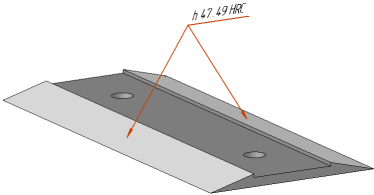
Example of placing a leader
See Also