|
Reference number |
Scroll |
To create a leader line, use the Reference number command  .
.

Step-by-step instructions
1.Specify the object for labeling a designation – an edge or face of solid or surface. The name of the part to which the selected object belongs will appear in the Objects field on the Parameter Panel.
In the graphic region, a phantom of designation is displayed. The final point of the first branch coincides with the point at which the object was specified.
2.Select designation position.
The reference number suggested by the system is displayed on the phantom of designation and in the Text field.
3.After specifying the designated object, the position of the designation plane is automatically determined. If necessary, you can change position of designation plane, by selecting a different base plane. The elements of the Placement group are used for this purpose.
4.Create the required number of leader line branches. More...
You can add objects to a symbol without creating additional branches. To do this, click in the Objects field, then select the desired objects in the graphic area. The selected objects will be highlighted, and their names will appear in the Objects field.
5.Configure the label parameters using the items in the Parameters group and the Additional Options section. The configuration is the same as creating a label in a graphic document, with the only difference being that you cannot rotate the shelf using the key <Ctrl>. More...
6.If necessary, set the name and color of the designation using the elements in the Properties section. More about color management of objects...
7.To complete the creation of the designation, click the Create object button.
After completing the described steps, the created positional leader line will appear in the graphic area, and its icon will appear in the Design tree.
8.To complete operation of the command, click Finish  .
.
|
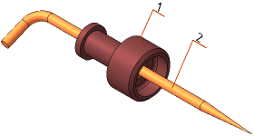
Example of labeling an reference number
See Also