|
Grid |
Scroll |
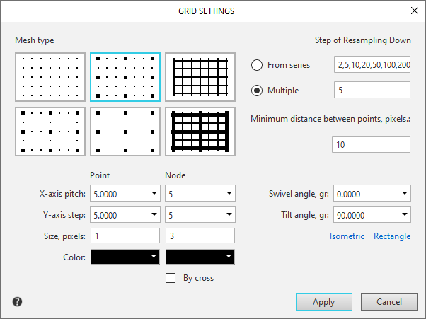
The appearance of the auxiliary grid displayed on the screen (in a graphic document or in a sketch) is configured in the Grid Settings dialog.

The element |
Description of setting |
||
Grid type |
The group of options allows to set the grid type. To select the required type, enable the matching option. |
||
Point |
The group of options allows to set the grid type. The controls are available when one of the dotted grid types is selected in the Grid Type group. |
||
|
Step by axis X, mm |
The field allows to set distance (in millimeters) between grid points in the direction of axis X of the current coordinate system. |
|
|
Step by axis Y, mm |
The field allows to set distance (in millimeters) between grid points in the direction of a y axis of the current coordinate system. |
|
|
Point Size, pxl. |
The field allows to set the grid point size in screen units (pixels). Only odd values are allowed. |
|
|
Color |
The button allows to select the grid point color in a standard color selection dialog. |
|
Node |
This group of elements allows you to configure the parameters of grid nodes. The controls are available if one of the grid types with nodes is selected in the Grid Type group. |
||
|
X-Axis Pitch of Nodes |
The field allows to set the number of grid points in which it is required to label nodes in the X-axis direction of the current coordinate system. |
|
|
Point Size, pxl. |
The field allows to set the grid point size in screen units (pixels). Only odd values are allowed. |
|
|
Point Size, pxl. |
The field allows to set the grid point size in screen units (pixels). Only odd values are allowed. |
|
|
Color |
The button allows to select the grid point color in a standard color selection dialog. |
|
|
Display node as crosshair |
Enable this option to make grid nodes be displayed as "crosshairs". With the option disabled, grid nodes are displayed as small squares. |
|
Step of Resampling Down |
The group of options determines the multiplicity of display of grid points in case of impossibility of their normal displaying (in a window with small image scale). |
||
From Series |
Enable this option to make the multiplicity of display of grid points be selected from the number sequence: 2, 5, 10, 20, 50, 100, 200, 500, 1000, 2000, 5000, 10000, 20000, 50000, 100000, 500000. It means that if you such a display mode that does not allow to display each point correctly, the screen will display every second point of the grid; as the scale is getting finer – every fifth, then tenth, and so on. |
||
Multiple |
The option sets a pitch of resampling down for grid points multiple to any integer number. For example, setting a step of resampling down multiple to 2means that with the reduction of images scale the screen first shows every second grid point, then – every fourth, then – sixth, and so on. |
||
Minimum grid spacing, pxl. |
The field allows to set the minimum distance (in pixels) among grid points. With the reduction of image scale, the distance (in pixels) between grid points on the screen is reduced accordingly. As long as this distance is greater than the set minimum distance, the resampling of grid does not occur. On subsequent reduction of scale, the grid is resampled down according to the set parameters. |
||
Rotation angle, deg. |
The field allows to set a grid rotation angle relative to axis X of the current coordinate system (in degrees). The angle is counted from the positive direction of X axis counterclockwise. |
||
Obliquity, deg. |
The field allows to set the angle (in degrees) between the cells sides, which defines the distortion (nonsquareness) of the cell. By default, it is set equal to 90 degrees (a rectangular cell). |
||
Isometric view |
Clicking this button automatically sets the rotation angle to 150 degrees, and the angle of distortion – to 60 degrees. A grid with such parameters is convenient to use for drawing of isometric images. |
||
Rectangular |
Pressing this button automatically sets a zero rotation angle and the angle of distortion to 90 degrees (a grid with a rectangular cell not turned relative to the X axis of the current coordinate system). |
||
After completing the grid settings, click Apply. If the settings were made for the current tab and the grid is enabled on it, the grid in the graphics area will be redrawn according to the specified settings.
To exit the dialog without changing the grid settings, click Cancel.
See also