|
Additional features when building rectangles and polygons |
Scroll |
A rectangle/polygon can be constructed as a single object or as several separate segments. The build option is determined by the state of the option Explode Object.
•If the option is disabled, a rectangle/polygon is constructed as a single object. Such an object is selected/moved/edited as a whole. This option is the default when working in a graphic document.
•If this option is enabled, the rectangle/polygon is divided into separate segments corresponding to its sides. Such an object cannot be selected/moved/edited as a whole — each segment is processed separately. This option is the default when working in the sketch.
If construction with the destruction of the object is performed in parametric mode, then besides segments — sides of the rectangle/polygon are also created:
•for a rectangle – the segments corresponding to its diagonals, and their point of intersection;
•for a polygon, a circumscribed or inscribed circle.
In addition, in the parametric mode, constraints are imposed on the objects obtained so as to maintain their mutual position.
|
|
a) |
b) |
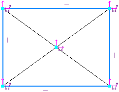
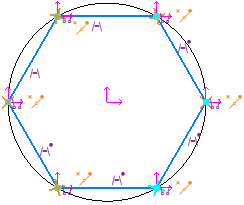
Constraints applied in parametric mode:
a) on the objects that make up a rectangle,
b) on objects that make up a polygon
|
If necessary, a rectangle/polygon, created as a single object, can be broken into segments using the command. Explode from the context menu. In parametric mode, the result of such an explosion (unlike creation with the option Explode object) is a set of segments constituting the sides of a rectangle/polygon, without additional objects and constraints. |

Constructing axis lines
By default, rectangles and polygons are drawn without axis lines.
To create an object with axis lines, enable the With Axes option in the Options Panel.
Axis lines are a system macroelement—a center mark. The center mark is not linked to the rectangle (polygon) and is not redrawn when the object is further edited (by changing parameters or position).
You can also add axes to a rectangle or polygon using the Center Marker command.
|
When working in parametric mode, the center mark is created as a constraint on the rectangle (polygon). |
If a rectangle is constructed using axes, creating a leader dimension from the midpoint of one of its sides presents a certain challenge. The reason is that, by default, the dimension is not associated with the rectangle in this case, which prevents it from being associative. To add a dimension to the rectangle, you can use local snap or temporarily prevent the rectangle’s characteristic points from coinciding with the axis line while adding the dimension. More details...
Selecting a line style
When creating objects, the current line style is displayed in the corresponding field on the Options Bar. To change the style, expand the Style list and select the desired option. Learn more about selecting a line style...
Saving settings
When creating a series of objects that share certain parameters (such as a common center or a common vertex), you can save the values of these parameters until the command is completed. To do this, after setting the parameter values common to all objects, click the Remember Status, then continue building. More about saving parameters...
Example. Constructing several rectangles with a common center.
1.Invoke the Rectangle by Centerpoint and vertex command.
2.Specify the common center of the rectangles.
3.Click the button Remember Status.
4.Specify the vertices in order and construct the required number of rectangles.
