|
Majority surface Parameters |
Scroll |
The elements of the Parameters Panel shown in the table are used to set the majority surface parameters.
Controls for majority surface parameters
Element |
Description |
|
Processing Method |
This group of buttons allows you to select one of the majority surface symbols: |
|
|
|
Not Specified, |
|
|
Delete material layer, |
|
|
Without material removal. |
Layout |
The button group allows you to add the following elements to the majority surface symbol: |
|
|
Use this button to enclose the roughness symbol in parentheses. Parentheses are used when roughness requirements are specified after final machining (product assembly). Clicking the button again removes the parentheses. In a graphical document, you can also insert or remove parentheses using the button on the context panel that appears when you select the surface roughness symbol in the graphical area. |
|
|
Use this button to insert a character «*» after the roughness symbol. Each time you press the button, another symbol is added. Insert a symbol into a graphic document «*» You can also do this using the button on the context panel that appears when you select a roughness symbol in the graphics area. Text formed from characters «*», You can edit with or without starting the editing process. In this case, on the Options Panel, in the Text group, changes are made to the Text after field. During the editing process, you can insert various characters and text. |
|
Along Contour |
This option allows you to add a circle as an auxiliary symbol to the surface roughness designation, indicating that the surfaces forming the contour have been machined identically. |
|
Leader |
The switch allows you to place the roughness symbol on the leader line shelf. •If the switch is set to position I (on), the roughness symbol is placed on the ledge of the leader line. The Parameter Panel contains settings for the leader line. •If the switch is set to position 0 (off), the roughness symbol is placed on the surface (or its extension). |
|
Landing |
This group of buttons allows you to set the orientation of the leader line so that the roughness symbol can be placed on it. It appears on the Parameters panel when the Leader switch is set to I (On). The following options are available: |
|
|
Right, |
|
|
|
Left, |
|
|
Top, |
|
|
Bottom. |
|
You can also change the orientation of a callout line shelf in the following ways. •To reverse the direction of the shelf, move the cursor to the right/left (if the shelf is horizontal) or up/down (if the shelf is vertical). •To rotate the leader, scroll the mouse wheel while holding down the <Ctrl> key. Changing the direction of the leader line toggles between the options for placing the surface roughness symbol on it. When further editing the roughness symbol located on the shelf, you can change the leader line parameters using the Leader Length and Leader angle fields (the angle of inclination relative to the x-axis of the current coordinate system). |
|
Arrow |
The drop-down list allows you to select the type of leader arrow. It appears on the Options Bar if the Leader switch is set to I (On). |


|
|
a) |
b) |
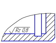
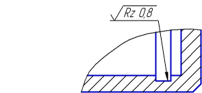
Placement of the majority surface symbol:
a) on the surface, b) on the leader landing
