|
Specifying objects for setting smart dimensions |
Scroll |
While using the Smart Dimension command, you can specify curves entirely, their characteristic points, and intersection points of the curves. A result of the command, i.e. the dimension created, will depend on the types and combinations of selected objects. If you select a segment (full curve), a simple linear dimension for distance between its ends is created. If you select a segment and a point, a linear dimension for distance from the segment to the point is created.
A document usually contains some snaps which activate when you hover the mouse pointer over objects. The result will contain:
•a point if, when selecting an object, the snap - Nearest Point, Midpoint, Intersection, or Center - was triggered,
•the curve, if the Point on Curve snap was triggered during object selection.
If no snaps were activated or snaps were disabled, the result contains the whole object (full curve).
|
Use the <Alt> key to temporarily disable snaps. Keep this button pressed when selection an object, if you need to provide full curve rather than single point. |

The tables below contain objects and combinations of objects that you can provide for the Smart Dimension command, and the resulting dimensions obtained in each case.
Linear Dimensions
Dimension Type |
Specified objects |
Examples |
|
Simple linear dimension |
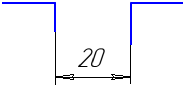
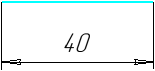
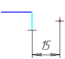
Two points; segment; elliptical arc. |
|
|
|
|
||
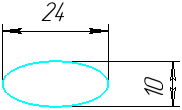
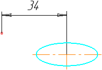
Ellipse. |
|
||
A point and an ellipse (or an arc of an ellipse). |
|
||
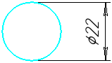
Circle (after the object is specified, move the cursor in the direction of axes of the current view coordinate system, or the absolute coordinate system for a fragment). |
|
||
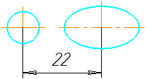
Two ellipses; circle and ellipse; circle and elliptical arc; ellipse and arc; arcs of circle and ellipse. |
|
||
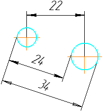
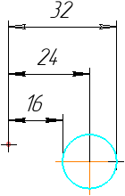
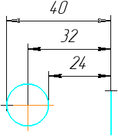
Two circles; two arcs; an arc and a circle. A dimension is created between the centers of the circles/arcs, or a dimension whose extension lines are tangent to the circles/arcs. You can select the desired option using the Previous Result |
|
||
Point and circle (or arc). Creates a dimension from a point to the center of a circle/arc, or a dimension with a leader line tangent to the circle/arc. You can select the desired option using the Previous Result |
|
||
Axis line/segment with the Centerline style and a point. |
|
||
Two objects: •segment and point, •two parallel segments, •segment and circle (or circle arc). You can also set dimension from line to point between two centerlines or segments with the Centerline style. |
|
||
|
Line segment and circle (or arc). Create a dimension from the line segment to the center of the circle/arc, or a dimension with a leader line tangent to the circle/arc. You can select the desired dimensioning option using the Previous Result |
|
|
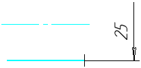
Angular Dimension Trimmed |
Two parallel line segments, one of which is an axis or has the Centerline style. |
|


Angular Dimensions
Dimension Type |
Specified objects |
Examples |
|
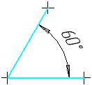
Simple angular dimension |
Two non-parallel rectangular objects of the following types: •segment (including a broken line segment, side of a polygon, etc.), •construction line, •axis of the absolute coordinate system or the view coordinate system, •centerline. |
|
|
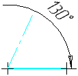
Angular Dimension Trimmed |
Two non-parallel objects, one of which is a centerline or a segment with the Centerline style, and the other is a rectangular object of any of the following types: •segment (broken line segment, side of a polygon), •construction line, •axis of the absolute coordinate system or the view coordinate system. |
|
Radial and diametric dimensions
Dimension Type |
Specified objects |
Examples |
|
Radial Dimension |
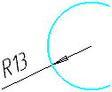
Circle arc (you can change dimension type to Diameter). |
|
|
Diameter Dimension |
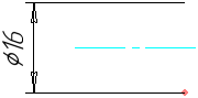
Circle (you can change dimension type to Radial). |
|