|
Broken-out Section |
Scroll |
Broken-out section is a cross-section made by the cutting plane in a separate, bounded place of the model. The broken-out section is built in the existing associative view. This view is regarded as the reference. Any closed line (circle, ellipse, closed Bezier curve, etc.) can be the border of the broken-out section.
Creation of the broken-out section is available for all associative views.
The broken-out section can be built if the following conditions are met.
•The reference view contains a closed line – the border of the broken-out section.
This line must be created in advance and be located inside the reference view (i.e., while building the line, the reference view must be current one); the line must not have self-intersections.
•The drawing has one more associative view for indication of the clip plane position on it. The plane of projections of this view must be perpendicular to the plane of projections of the view in which the broken-out section is built.
To indication the position of the clip plane, you can use one of the views of the drawing, or a view created specially for building the broken-out section. In the latter case, after creation of the broken-out section, the view can be hidden.
To build a broken-out section, follow these steps.
1.Run the Broken-out Section  command.

2.In the reference view, specify the closed line that restricts the broken-out section. Its name will be shown in the Border field on the Parameter Panel.
Below this field, there will appear the settings of parameters for the broken-out section, and in the graphic region of the drawing – a phantom of a trace of the clip plane. This phantom represents a straight line and is shown in the graphic region when the cursor is moved above the other – not reference – view of the drawing if the plane of projections of this view is perpendicular to the plane of projections of the reference view.
3.On the Parameter Panel, the Cut/Section toggle switch is displayed. By default, it is in the Cut position. If necessary, you can change the image type by setting the toggle switch to the Section position.
|
The Cut/Section toggle switch is there on the Parameter Panel, if the reference view of the broken-out section being created is not a slice (section). Otherwise, the type of image coincides with the type of image in the reference view, so the switching is impossible. |

4.Set the name and number of the view using the respective fields. The number of the view can be any number other than the numbers of already existing views.
5.Set up the hatching parameters. Details...
6.Specify the position of the cutting plane with a mouse click.
Creation of the broken-out section will be completed. It will be displayed in the reference view. In the Drawing tree, a new object – broken-out section subordinate to its reference view will appear.
|
By default, all the parts which fell within the cutting plane are shown in cross-section. You can also make some of them uncuttable ones. |

|
|
|
a) |
b) |
c) |
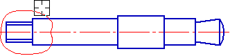

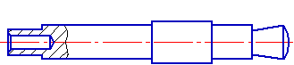
Building a broken-out section
a) indication of the line that restricts the broken-out section,
b) indication of the position of the cutting plane, c) command version results.
Managing the broken-out section display
In the context menu of the broken-out section view, there is the Broken-out Section command which controls the display of broken-out section in a view. The checkmark next to the command name means that broken-out section display is enabled.
You can enable and disable the display of the broken-out section using the Broken-out Section command or the 'eye'  icon in the Design Tree.
If the display of the broken-out section is disabled, then the reference view and the created in it to restrict the broken-out section are shown in the initial status.
To make this line not to be displayed in the graphic area, move it to another layer and hide it.
|
By default, all parts that fall within the section plane are shown in section. If necessary, you can make some of them non-sectioned. |
|
|
|
a) |
b) |
c) |
Creating a local section
a) specifying the line that defines the section,
b) Specifying the position of the cutting plane, c) The result of executing the command
Deletion of the broken-out section
To delete a broken-out section, invoke the Delete Cut command from its context menu.
This command results in that only broken-out section is deleted. The line selected as its border remains in the reference view. You should delete it separately.
See Also
