|
Constructing a shell |
Scroll |
To transform a solid to a shell, use the Shell  command.

Step-by-step instructions
1.Select the faces to be deleted in the model's graphics area.
You can select a single face or a group of faces that meet a specific condition with a single selection. Use the Quick Access Toolbar to specify the condition.
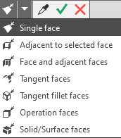
The selected edges are highlighted, and their names are displayed in the Removable faces field on the Parameter Panel.
2.For faces that you don't delete, specify the direction of adding material relative to the solid surface. To do this, set the Direction toggle switch to the Outward or Inward position.
3.Specify the general shell thickness in the field Thickness.
The shell is displayed in the graphics area as a phantom.
5.If necessary, specify thickness for an individual face/faces using the Variable Thickness toggle.More details on specifying thickness for an individual face...
5.If necessary, set the name of the shell and its surface properties in the Properties section. More details on the management of the color and optical properties...
6.To complete the operation, click Create Object  .
.
After confirming the operation, an image of the thin-walled shell will appear in the graphic area, and the corresponding iconwill appear in the Design Tree.
7.To complete operation of the command, click Finish  .
.
Tips
•You can set the shell thickness and the material adding direction in the graphic area using defining points (to learn about defining points, see section Defining Points of Objects).
•To set the linear parameters, you can use the geometrical calculator.
•You can assign tolerances to the values of the operation parameters expressed in linear values. To do this, call the Tolerance command in the menu of the required parameter, or click  in the parameter field (the icon is displayed if a tolerance is assigned to the parameter value). More details on assigning tolerance...
See Also
