|
Angle sides configuration |
Scroll |
To set angular dimensions of any type, you can specify:
•rectilinear objects – angle sides,
•points, when connected, forming the sides of an angle.
The following can be used as a rectilinear object (hereinafter the "segment"):
•segment, segment of a broken line, side of a polygon,
•Centerline type object,
•constructive line,
•axis of the absolute coordinate system or of the view coordinate system; in the parametric mode, specifying axes as angle sides has specialties.
Options of specifying angle sides for setting angular dimension are described below. See figures for examples. The sequence of objects selection is shown in the figures with numbers in parentheses.
Specifying segments as angle sides
Segments are specified in the base object selection mode. This mode is enabled by default. At the same time, on the Parameter Panel to the right of the Objects field, the Selection of Main Object button is pressed  .
.
Snaps are disabled in the base object selection mode.
Sequentially indicate the segments — the sides of the angle. One of the end points of the first segment is used as the first dimension snap point, and{1}one of the end points of the second segment – as the second snap point. The position of the vertex of the angle is calculated automatically.
This re-enables snaps. You can use them to set the position of dimension text.
Names of selected segments are displayed in the Objects field on the Parameter Panel. If you need to re-select a segment, remove its name from this field.
|
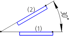
Example of setting angular dimension to two segments
|
If you need to specify a segment with the base object selection disabled (Selection of Main Object button is deselected), you can use one of the following methods: •specify a segment while holding down <Alt> (to disable all snaps temporarily), •disable snaps that prevent the segment from being specified, e. g. the Point on curve snap, and move the mouse cursor to the segment avoiding any snaps from being triggered. |

Specifying the angle vertex and points on its sides
If you need to set an angular dimension to points, release the Selection of Main Object button.
Specify the point that will be the vertex of the angle, and then the points on its sides — the dimension snap points. Their coordinates appear in the corresponding fields of the Coordinates group on the Parameter Panel. If you need to specify a point again, unfix the field with its coordinates.
|
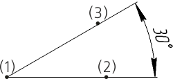
Example of setting angular dimension to three points
|
Points cannot be specified if all snaps required to specify points are disabled in the document (e. g. Nearest point, Intersection, etc.). Additionally, if no snap is actuated when the mouse pointer is hovered over the object, then the object will be specified instead of the point. |
Setting one angle side using segment and the other side using points
If you need to set an angular dimension by setting one of its sides using a segment and the other side using two points, use one of the following methods:
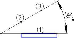
•in the base object selection mode (the Selection of Main Object button is pressed) — specify a segment, press the Selection of Main Object button and specify two points,
•in the points selection mode (the Selection of Main Object button is deselected), specify a segment while holding down <Alt> or placing the mouse cursor on the segment without actuating any snaps and then select two points.
One of the end points of the specified segment is used as the first snap point, and one of the specified points – as the second snap point. The segment and the straight line going through the specified points form an angle. The position of the angle vertex is auto-calculated.
|
Example of setting angular dimension to a segment and two points