|
Overview |
Scroll |
The extrusion element is formed by moving the section along a straight guideline to one or both sides at a given distance. For example, the following figure shows an element formed by extruding a sketch in a direction perpendicular to its plane.
|
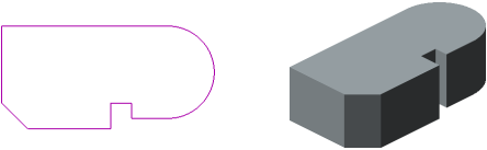
Sketch and Extrusion Element
The extrusion element can be an independent solid, but it can be glued to the solid or cut out of it.
To create a new extrusion solid or to glue an extrusion element to an existing solid (i.e., to add material), use the Indentation element operation, and for cutting the extrusion element out of the solid (i.e., to remove material), the operation Cut Extrusion Solid operation.
You can use a face, a sketch (a sketch area), an edge, a 3D curve or an arbitrary combination of several of these objects as a section of an extrusion element.
Specifics of objects selected as sections determine possibilities of building an extrusion element — solid or thin-walled; with slope or without it. Examples of some building options are provided in the following figures.
|
|
|
a) |
b) |
c) |


Face extrusion
a) section (cylindrical face); b) \solid element; c) thin-walled element
|
|
a) |
b) |
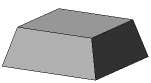
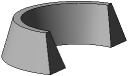
The slope of the side faces of the extrusion element
a) solid; b) thin-walled
|
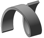
Extrusion element with spiral section
See Also