|
Flat Pattern Drawing |
Scroll |
KOMPAS-3D allows to display sheet part flat patterns in associative views of drawings in accordance with the stored flat pattern parameters.
Forming flat pattern image is available when you create the following associative views:
•Arbitrary view,
•Projection view,
•View in arrow direction.
|
This section is intended for users with experience in creating associative views. Creation of these views is not discussed in detail here. If you do not know methods of working with associative views, please refer to the section Associative views. |

To form the flat pattern display in the view, enable the Flat pattern option on the Parameters bar. The option is displayed on the Parameters bar if the flat pattern parameters are set in the model.
Drawing of bend lines is managed in the Lines. Note that automatic drawing of bend lines on the view is possible, if the plane of projections of this view is parallel to the flat faces obtained when the bends are unfolded.
To select the correct projection plane for the view containing a flat pattern, you should know how the flattened sheet part is located relative to the main projection planes. This location depends on which of the faces of the part or planes is specified as the view’s plane during flat pattern configuration.
Let’s consider selection of the projection plane to display the sheet part flat pattern shown in Fig. a.
|
|
a) |
b) |
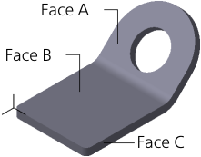
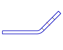
Sheet part: a) in Isometry XYZ projection, b) main view
Let’s assume that the main view of the model (Figure b) is already built in the drawing. Now we need to create a flat pattern.
In this case, it is better to form an arbitrary view of this model in the drawing.
When creating an arbitrary view the Flat pattern row becomes available in the Flat pattern list on the Parameters bar. Selection of this row means that the projection plane of the view will be parallel to the face specified as the view's plane when configuring the flat pattern parameters in the model.
If Face A (see Fig. a) was specified as the fixed face, in order to create a flat pattern display, select the Flat pattern.
If Face B was specified as the fixed face, in order to create a flat pattern display, select the Top view, Bottom view or Flat pattern orientation.
If Face C was specified as the fixed face, in order to create a flat pattern display, select the Top view or Bottom view orientation.
Enable flat pattern formation or drawing of bend lines, configure the remaining view properties, then confirm its creation.
Note that the arbitrary view with the flat pattern display is automatically assigned a designation containing a conventional graphic designation "unfolded".
|
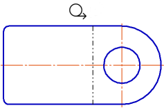
Flat Pattern of the Sheet Part
|
The use of the automatically generated Flat pattern orientation is not mandatory. If required, you can manually create a desired orientation in the model and use it for constructing a flat pattern in the drawing. |

When you create a view in the arrow direction and a projection view, you are not able to select orientations in the list because the position of projection planes of these views depends on the visual direction. When selecting this direction, consider the location of the flattened sheet part.
|
A sheet part is always displayed on cuts (sections) in the same state as in the reference view. If the state of a sheet part changes in this view (flat pattern enabled or disabled), the cuts (sections) are automatically rearranged. |