|
Notes on Unfolding and Folding |
Scroll |
Modifications of sheet model that prevent folding or unfolding bends
When unfolding and folding bends using the Unfold  and Fold
  commands, as well as when using the Flat Pattern
  command, the following circumstances must be considered.
•If the bend is not affected by other elements, you can always unfold or fold it.
•Elements affecting the bend can be located in such a way so that it becomes impossible to unfold or fold the bend.
|
|
|
a) |
b) |
c) |
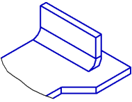

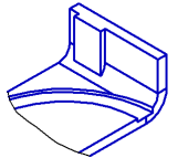
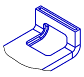
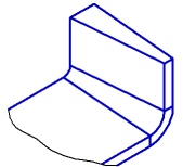
Examples that make unfolding of the bend impossible:
a) a plate is created after a bend creation; b) a cut with a sketch on a lower part face; c) stuck and cut conceptual masses
•Operations resulting in full rebuilding of edges and/or faces of the bend will always make its unfolding or folding impossible.
|
|
a) |
b) |
Examples of operations that make unfolding of the bend impossible:
a) shell, b) slope
•If the sheet part consists of several portions (for example, it is split by the cutting operation), then changing the state of the bends becomes impossible. To unfold or fold bends, first make a part as whole by editing the existing elements or creating new elements which will join the portions.
"Behavior" of dimensions and designations during bending and unbending
When bend states change in a sheet model, all dimensions and designations in it are rebuilt if the corresponding source objects are intact and still usable for creation of those dimensions and designations (otherwise, the designations/dimensions cannot exist and are marked as erroneous, see below). But you should always keep in mind the following features.
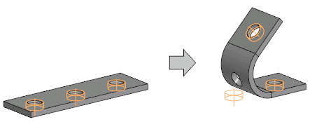
•If the base object of designation is on a bend, then upon unbending or bending this bend, the designation does not rebuild, i.e. remains in the initial position. This also does not create errors in the Model tree.
For example, in a sheet body, a hole with an axis and thread was created, and then an array of these holes was constructed. After bending this sheet solid the axis and the thread of the hole, located at the bend, stay in the previous positions.
|
•After transitioning into the flat pattern mode, some dimensions and designations may be marked as erroneous in the Design Tree. This happens in those cases, when the objects used for dimensions or designations:
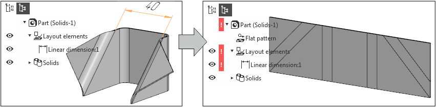
•moved to a position unsuitable for executing the operation, for example:
in the bent part, the dimension between parallel ribs was set, and after unbending, these ribs became non-parallel.
|
•Ceased to exist, for example:
when creating the dimension, a cylindrical face of the folded bend was specified, i.e., the axis of the cylinder was used for dimensioning. After unfolding, the cylindrical face became flat, causing its axis to cease to exist.
|
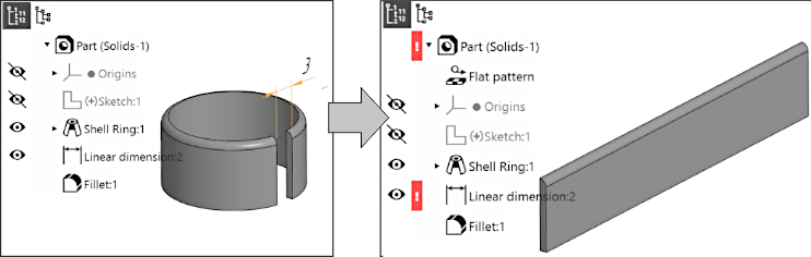
Please remember that such errors as described above may be created by the Unfold or Fold command execution — despite the fact that operations using the changed objects are located in the Tree above, not below the unfolding/folding operation.
|
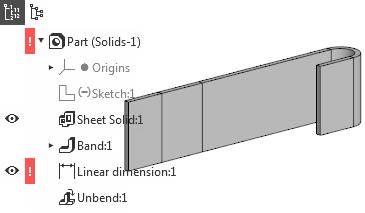
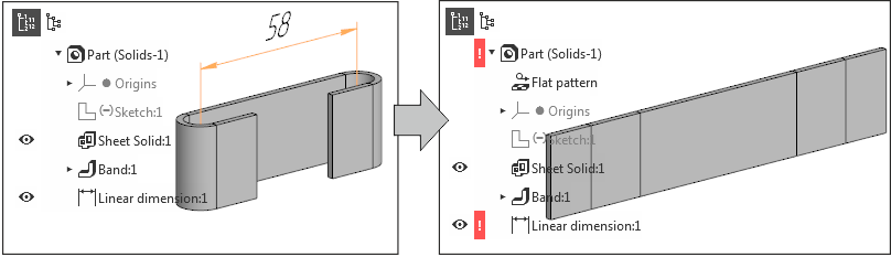
Now let's consider a case when an error occurs in a sheet body due to the disappearance of objects used for dimensioning.
Let's say that in the part with a flange, the width of the gap was dimensioned. Then, rounding was performed, as a result of which the vertices on which the dimension was based disappeared. Immediately after this, there is no error in the model. However, if the flange is unfolded, the dimension is marked as wrong, since the unfolded part — due to rounding — does not have the necessary vertices and the dimension cannot exist. Accordingly, in the absence of rounding, such an error will not occur, since the vertices necessary for dimensioning will be present in the unfolded shell.
|