|
Graphic region |
Scroll |
Graphic region takes up the greater part of the KOMPAS-3D window. In this region, the content of the current document is displayed – the 3D model of a part or assembly, graphic objects constituting the drawing or tile, the text of a text document, the BOM table.
The system information messages and icons of operating modes are also shown in the graphic area (for example, the mode of component in-place editing, the mode of assembly components explosion, the print preview mode, etc.).
|
Graphic region while working with a model
Info messages by default are displayed in the bottom right-hand corner of the graphic region. You can tune the point of its display, as well as other parameters of messages using the dialog Pop-up messages.
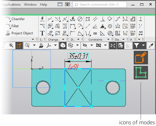
Icons of modes are used for informing the user of the current operating mode and way of exiting it. In fact, the icon of a mode – is an indicator which is displayed in the graphic region of a document while the system is switching to some mode or the other. Clicking a mouse on an icon means exiting a mode. After that, the icon disappears.
In the graphic region of a document, several icons can be displayed simultaneously. For example, a model can run in the in-place editing mode wherein the sketch editing mode can be started.
Icons are displayed for the following modes:
•sketch;
•editing technical requirements,
•in-place editing of an asset,
•editing a graphic macro-element,
•editing of BOM items,
•recalculation of dimensions based on tolerances,
•preparing data for the report,
•filtration of rows in the data processing window for the report,
•editing the source file of the embedded tile,
•arbitrary face editing ("Spline form" mode),
•flat pattern,
•spacing of assets,
•print preview.