|
Examples of using command |
Scroll |
The constructions described in the examples are performed in parametric mode. Objects are built arbitrarily indicating the starting and ending points. The parameters of the objects – the length and angle of inclination of the segments, the radii of the arcs – are determined by dimensioning.
Example 1
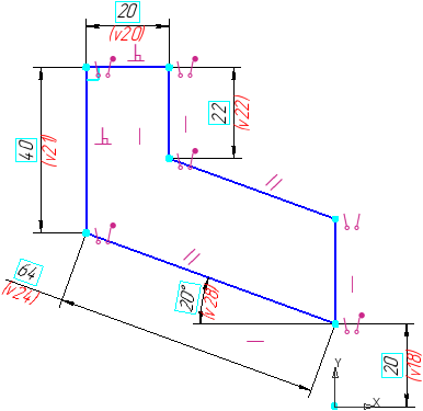
It is required to create sketch of the bushing shown in the figure.
|
Step-by-step instructions
1.Run the Autoline  command.
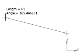
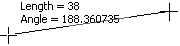
2.Specify the arbitrary starting point of the first segment. The segment will be located at an arbitrary angle.
|
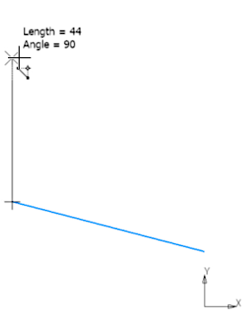
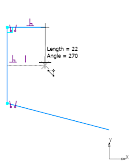
3.The next segment should be located vertically. Specify its end point using the binding Alignment.
|
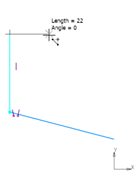
4.Build the next segment perpendicular to the previous one. To that end, press Select Base Object  button and indicate the previous segment. Then specify the end point of the segment to be created.
|
5.Next, build a vertical segment using the binding Alignment when specifying its end point.
|
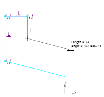
6.The next segment should be parallel to the first. Click Selection of Main Object and designate the first segment. Then indicate the approximate end point of the segment to be created.
|
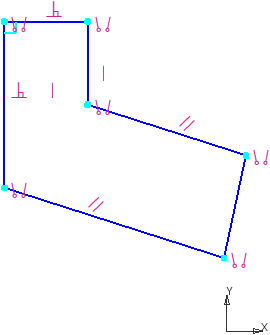
7.As the end point of the last segment, specify the starting point of the first one. The resulting segment is not vertical. This will be corrected further.
|
8.To complete the Autoline command, click Finish  .
.
9.To place the last segment of the chain vertically, select it, call the Alignment  command and specify a vertical line that defines the alignment direction (method of defining the direction — By straight lines).
10.Specify the required dimensions. Sketch is complete.
|
Example 2
It is required to create sketch of the groove shown in the figure.
|
Step-by-step instructions
1.Run the Autoline command.
2.Specify the starting point of the first segment. The segment will be located at an arbitrary angle.
|
3.The next segment of the chain should be an arc. Press the Arc  button in the Segment Type group.
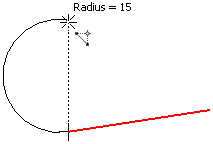
4.By default, the arc is constructed tangential to the previous segment of the chain. Therefore, after changing the segment type, the segment created earlier is automatically selected to construct a tangent arc. Leave the segment selected. To build an arc, specify its end point located on the same vertical with the starting point. To do this, use the Alignment snap.
|
5.Next, you need to build a segment. Change the segment type  .
.
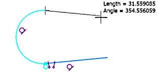
6.To place the segment tangentially to the arc, click the Select base object button and specify the arc. Then indicate the approximate end point of the segment.
|
7.Change the segment type again.
The created segment will be automatically selected to build a tangent arc.
8.As the end point of the arc, specify the starting point of the first segment.
|
9.To complete the Autoline command, click Complete .
10.Set the touch of the first segment and the last arc. To do this, run the Tangency  command and specify the required objects.
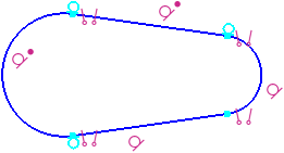
11.To ensure symmetry, the centers of the arcs need to be aligned horizontally. To do this, call the Alignment command and specify the centers. Click on the phantom horizontal line in the graphics area.
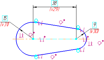
12.Specify the required sizes, and impose constraints. Sketch is complete.
|