|
Movable subassemblies |
Scroll |
Assembly model can be inserted into another assembly model as a component — subassembly. You can change position of a subassembly in the parent assembly, but you can't move or rotate its individual components. This restriction may impede placing assembly components, especially if any mating with the subassembly components are expected. To address this problem you can make a subassembly "movable".
Moving subassembly is a subassembly for which you can change components' position while working with its parent assembly. Movable subassemblies are used to simplify assembly creation by easily changing positions of its components.
|
You should mark a subassembly as movable only in those cases, where its components should be moved for easier placement of components in a higher level assembly. |

Components of a subassembly may be linked by Matings, which impede the movement of these components. When you make a subassembly movable, all matings from it are added to a current assembly. You may exclude them from calculations to move components without restrictions. This does not affect the source file of the subassembly.
If the source file of the subassembly defines a value range for a mating, there is no need to exclude that mating from calculations, since it already allows to move the components within the defined range. Those matings are important to avoid collisions or dispersion of the components, when you move them. For example, the At Distance This range is convenient to use for ensuring linear displacements.
The figure shows an assembly with three components: a subassembly Hydraulic Cylinder and parts Plate and Lever (figure a).
To move the lever to a desired position we need to move a stem in the hydraulic cylinder also. The position of the stem is controlled by the At Distance mating.
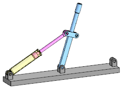
•If the distance between the rod and the bottom of the cylinder is strictly defined, then the movement of the rod is impossible. In that case you need to switch off the mating in order to move the stem. We can achieve exactly that by making the subassembly movable and excluding the mate from the calculation At Distance. Now you can move the hydraulic cylinder stem with the linked lever to the required position (see Figure b).
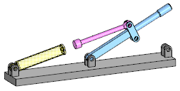
When moving the lever with the excluded mate from the calculation, ensure that the rod does not go beyond the limits of the cylinder (Fig. C).
•If the distance is specified by a range of values, the rod can move within this range. Lets make the subassembly movable, to enable the stem movement within the current assembly. Now you can move the hydraulic cylinder stem with the linked lever to the required position (see Figure b).
The displacement of the rod is performed only within the boundary distances specified in the mating. This helps to avoid mistakes while changing components' positions.
|
|
|
a) |
b) |
c) |
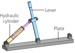
Using a movable subassembly for modelling:
a) initial components position;
b) desired components position;
c) component dispersion, which might happen after excluding the mating from calculations.
|
Movable subassemblies are also useful to examine the possible movements of assembly components. You can use simplified subassemblies with small number of first-level matings. |
