|
Overview |
Scroll |
The slope creation operation is usually performed at final stages of design. For example, a small slope is given to separate faces of a solid in cast models to ease taking out moldings from forms.
The following options are available for creating a slope.
|
Plotting of slope from the base
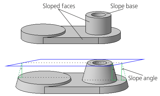
When constructing a slope, you specify the base of the slope, the sloped face, and the slope angle.
Slope base is a face of the body, the shape, dimensions, and slope angle of which do not change after performing the operation. Any flat face, which is not parallel to the sloped plane, can be used as the slope base.
Sloping face is the face whose angle of inclination with respect to the base will change as a result of performing the operation. This can be a plane face or a cylindrical face.
The slope angle vertice is located on the intersection line of the sloped face and the base or their extensions. The angle is measured from the perpendicular to the base. The result of running the command depends on the relative position of the base and the sloped face.
|
Building a slope from the base line
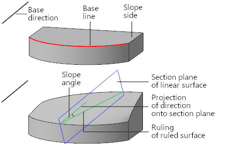
When plotting, you should specify the base direction, base line, slope side, and slope angle.
Base line is an edge or a chain of edges of a solid. Base line is the starting boundary of the sloped face (face).
Base direction is the direction determining the orientation of the generatrix surfaces of the draft face.
Inclination side is the edge adjacent to the baseline that will be changed after the operation is executed. The face surface will represent a linear surface by curve and direction, built along the base line considering the base direction. The slope angle is measured from the projection of the object determining the base direction onto the section plane of the ruled surface. More details about surface construction...

If required, the edge serving as the base line is extended so that the striated surface has a dimension sufficient to intersect with the adjacent faces. If the base line represents not one edge, but a chain of edges, then the replacing linear surface is built for each face located on the inclination side. The remaining faces of the solid are modified so that to keep the solid whole.
You can also slope the face while editing parameters of an extrusion element. But this method is different in essence from the slope creation operation:
•when creating a slope, you can slope separate faces, and when extruding with the slope all side faces of the element are sloped,
•creation of a slope does not change the position of elements which are subordinate to the sloped faces, and when editing an extrusion element sloping of its faces also "slopes" objects which are subordinate to these faces.
|
The slope creation operation is applicable to both solid faces and closed surface faces. Closed surfaces include: •extrusion, revolution, by path, By sections, created with the Closed Surface option enabled, •surfaces resulting from assemblies surfaces. |
