|
Overview |
Scroll |
KOMPAS-3D allows you to create two bends by a straight line in a sheet part relative to the flat face of this part. The specified line and face are a bend base line and an incision base face.
You can use the following as the bend base line for the incision:
•a segment of the sketch built on the outer or inner flat face of the sheet element,
•segment of the broken line,
•an auxiliary axis,
•a rectilinear edge of the mass element or surface.
|
If a segment or polyline segment is used as the bend base line, and a face to be bent has a complex shape, for correct construction of the incision it is recommended to position the bend base line so that it directly goes along all portions that have to be bent. |

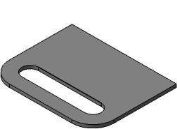
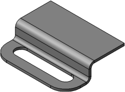
The incision design result depends on the relative position of the base face and the bend base line. As a general rule: you can fold that portion of the sheet part to which a base face or a portion of the base face fully or partly containing the bend base line belongs.
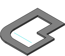
The Figures show variants of incisions. In all examples, a top flat face of the sheet part is used as the base face; the bend base line is shown as thick.
|
|
a) |
b) |
|
|
c) |
d) |
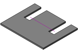
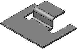
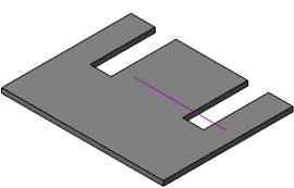
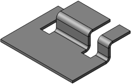
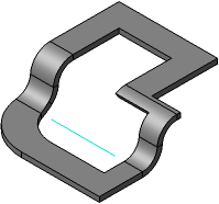
Dependence of the incision construction result on the bend base line position
a), c) variants of positions of the base line,
b), d) respective design results
|
|
a) |
b) |
Using an edge as the bend base line of the incision
a) position of the edge, b) construction result
|
|
a) |
b) |
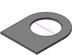
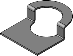
Incision in the part with a hole
a) position of the bend base line, b) construction result
|
|
a) |
b) |
Using a construction axis as the bend base line of the incision
a) position of the axis, b) construction result
|
A construction axis is infinite. Therefore, when selecting an axis as the bend base line it is irrelevant whether the representing segment has common points with the base face. For correct construction of the incision, it is sufficient if the axis extension has common points with the base face. |

See Also