|
Segmentation |
Scroll |
You can segment arcs of circles and ellipses in the contour (contours) of the shell ring.
Segmentation is replacement of curvilinear portions of the shell ring contour with approximating polylines consisting of segments of equal length. Bends of the specified radius are created in the vertices of a polyline. As a result, a bend corresponding to an arc in the sketch is replaced with a set of bends. An example of the shell ring segmentation is shown in the Figure.
|
|
a) |
b) |
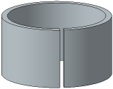
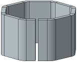
Example of shell ring segmentation
a) original state, b) result of segmentation
You can enable and configure segmentation in the Segmentation section (the section is present on the Parameters bar if the shell ring contour contains arcs of circles and/or ellipses or the contour is a circle/ellipse).
1.Set the Segmentation toggle switch to I (enabled). The controls to configure segmentation will appear on the Parameters toolbar.
2.Select a segmentation method by clicking the required button in the Method group and set the parameter for the selected method (see Table).
Description of segmentation methods
Method |
Parameter defining the number of polyline segments |
Scheme of segmented contour formation |
|
|
By number of Segments |
In the Number of Segments field, the number of segments of the approximating polyline is set. |
|
|
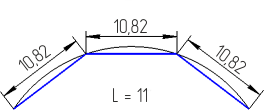
By segment length |
In the field Segment Length, the maximum length of the segment of the approximating polyline is specified. |
|
|
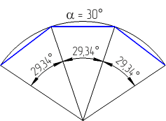
By segment angle |
In the Angle field of the segment, the maximum value of the central angle of the arc segment is specified in units of angle measurement. |
|
|
By linear deviation of segment |
The maximum distance between the segment arc and the segment of the approximating polyline is set in the Linear Deviation of Segment field. |
|


The number of segments can take integer values between 2 and 1,000 (if the shell ring contour is a circle or ellipse, the minimum number of segments is 3). The segmentation value should provide the number of segments in this range.
During setup, you can switch between methods. The value will be recalculated and displayed in measurement units according to the selected method.
If the shell ring contour contains more than one arc, you can configure segmentation for each arc separately.
1.Set the Same Parameters toggle switch to 0 (disabled). The Curves list with contour arcs will appear on the Parameters bar.
2.Select a row with the number of the required arc and set the segmentation parameters. When the row is selected in the list, the corresponding portion of the contour is highlighted in the graphics area.
To cancel arc segmentation, disable the option next to its number in the list.
The Figure below shows a shell ring with its contour containing a segment and two arcs. One of the arcs is segmented, while the other is not.
|
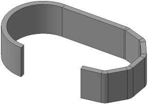
Example of the shell ring with segmented and non-segmented portions
Notes on Segmentation of Curves at the Bases of the Linear Shell Ring
Contour arcs of the ruled shell ring in the Curves list are named by the following template: N.n, where N is the number of the base, n is the number of the curve at that base.
If two arcs on different bases of the ruled shell ring are opposite each other (i.e. make a pair), the segmentation parameters are set for one of these arcs and applied to both of the arcs. The arc for which the segmentation parameters are set is the leading arc.
The number of the driven arc is added to the number of the leading arc in the Curves list. The controls to configure segmentation for the driven arc are not available.
If it is required to set the segmentation parameters on the driven arc, select the row with the number of this arc from the Curves list and click the Set Segmentation Parameters on the Current Curve button  to the right of the list (the button appears after selecting the arc in the list).
|
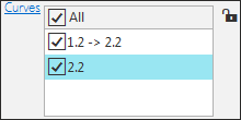
List of arcs at the bases of a ruled shell ring