|
Overview |
Scroll |
When building a model with the help of some operations, you can select the result of the operation and set its area. These actions are performed if the element created by the operation can modify objects in the model in different ways. For example, the extrusion element can be created as a separate solid or combined with the solid already existing in the model; When building a cutout in the sheet solid, you can select which part of the solid to leave – inside the specified contour or outside.
Operation result determines which transformation of objects will be performed after its completion – the union of solids, the subtraction of one solid from another, or the absence of transformations (in the latter case, the new element will be built as a separate solid).
Operation application area includes a set of objects that are converted as a result of the operation. An operation application area may include solids, or components, or both.
When adding material to the model (for example, when gluing elements), the area determines the objects with which the created (edited) element will be combined, and when deleting (for example, when cutting elements), objects whose material will be deleted as a result of the operation.
Suppose there are three solids in the model. On the upper face of solid 1, a sketch was created for the extrusion operation – a circle (see fig. A). Method of calculating the depth of extrusion – Through all. An operation application area may include any of these solids in any combination. Let’s say the area is solids 1 and 3.
|
|
|
a) |
b) |
c) |
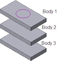
Extrusion operation application area:
a) the initial state of the part and the sketch of the operation;
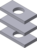
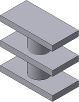
b) the result of cutting; c) the result of gluing
•If the extrusion element is cut, then as a result of the operation, a hole will appear only in solids 1 and 3 (see fig. B). Although the extrusion element passes through solid 2, it remains intact, since it is not included in the operation application area.
•If the extrusion element is joined, then we get a new solid consisting of solids 1 and 3 and the extrusion element (see fig. C). Although the extrusion element passes through solid 2, it remains intact, since it is not included in the extrusion operation application area.