|
Overview |
Scroll |
Corner capping is a modification of two adjacent bends and their extensions, where they match each other flush or with the given gap.
|
|
|
|
a) |
b) |
c) |
d) |
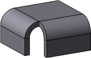
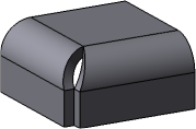
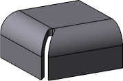
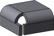
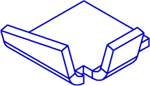
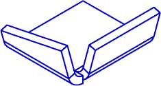
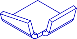
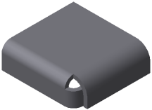
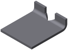
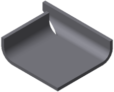
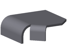
Corner capping
a) initial part state, b), c), d) variants of corner capping
Flat portions of the sheet part modified when the corner is capped are called sides of the corner.
Adjacent are called bends having a common edge located as shown in Figure below.
|
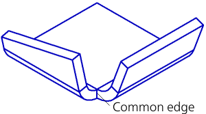
Adjacent bends
Thus, bends with reliefs, as well as bends shifted relative to each other, are not adjacent. Their respective corners cannot be capped.
|
|
|
Examples of non-adjacent bends
In some cases, adjacent bends have the parameters and are located relative to each other in such a way that makes corner capping impossible. Examples of such bends are shown in Figure below.
|
|
|
|
Examples of adjacent bends between which corner capping is impossible
|
For correct construction of corner capping, it is recommended that radii, angles and lengths of extensions of adjacent bends should be equal pairwise. |

|
You cannot apply the corner capping command if a sheet part consists of several portions (for example, it is split by a cut operation). To apply a corner capping operation, it is necessary to make a part as whole by editing the existing elements or creating new elements which will join the portions. |

See Also