|
Thin-walled element |
Scroll |
Elements that are obtained by extrusion, rotation, sectional or trajectory drawing and some other operations can be solid and thin-walled. Examples of solid and thin-walled elements are shown in the figures Extrusion of a surface, Rotation of a face, Element by sections.
Depending on the type and shape of the section, as well as the parameters of the operation, the resulting element can be either both solid and thin-walled, or only thin-walled. For example, when constructing an extrusion for a closed sketch, both solid and thin-walled elements can be obtained, and for an open sketch, only thin-walled elements can be obtained.
To select between solid/thin-wall options, the Thin-wall element switch located in the section with the same name is used. The switch can be in the following positions:
•position I (enbled) — a thin-walled element is created,
•position 0 (disabled) — a solid element is created.
If a solid element is created, no additional parameters need to be set.
If a thin-walled element is created, it is required to define the direction of wall construction and its thickness (see below).
A thin-walled element is a hollow element without ends. It is formed by adding a layer of material to the surface created by the contour movement. The thickness of the material layer is defined by the user.
|
The resulting element may not be «thin-walled» in the literal sense of the word. The concept of «thin wall» is introduced conventionally to distinguish a hollow element from a solid element. |

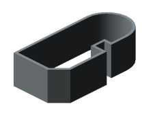
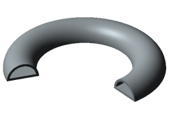
Examples of thin-walled elements are shown in Figures.
|
|
|
|
|
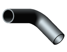
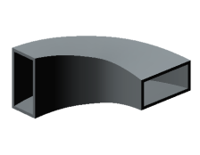
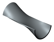
Examples of thin-walled elements
The parameters of the thin-walled element are configured in the Thin-walled element section .
Procedure
1.Set the Thin wall element switch to position I (on).
2.Determine the direction of addition of a layer of material and the thickness of that layer by one of the following methods.
•In one direction:
•forward direction — enter a positive value in the Thickness 1 field, while Thickness 2 must be zero,
•reverse direction — enter a positive value in the Thickness 1 field, while Thickness 2 must be zero.
•In two directions — enter non-zero values in the Thickness 1 and Thickness 2 fields. One of the values may be negative. The negative thickness is measured in the opposite direction to the positive and indicates the removal of material. This allows you to build a thin-walled element, separated from the original surface (see the figure below under the letter "b"). For correct construction, the specified negative value should be less than the positive one in absolute terms.
|
The values contained in the Thickness 1 and Thickness 2 fields can be swapped using the Swap When adding a layer of material in one direction, this button actually reverses the direction. |

•Symmetrical on both sides — set the Symmetric thickness switch to the position I (enabled) and enter the total thickness in the Thickness field. Only positive values are allowed.
|
|
a) |
b) |
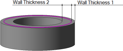
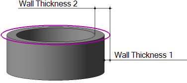
An example of constructing a thin-walled element during extrusion
(Material is added in two directions; the section is shown by a thick line)
a) wall thickness 1 and wall thickness 2 are positive;
b) wall thickness 2 has not changed, and wall thickness 1 has received the opposite sign
|
If the side walls of a thin-walled extrusion element have a slope, the specified thickness is observed in the section plane and planes parallel to it. |
