|
Contour |
Scroll |
Use the Create contour command  to build a contour consisting of parts of intersecting geometric objects.

Step-by-step instructions
1.Before specifying the parts of the contour, select the order in which the non-branching nodes are traversed — nodes where there is only one direction of further movement. To do this, move the switch Method of passing nonbranching nodes to the required position:
•Automatically — when specifying an object, the object itself and neighboring objects/chains of objects connected by non-branching nodes are selected.
•Manually — each contour segment is indicated in the graphics area.
2.Specify the geometrical object (or its part) from which you want to start contour traversal. A phantom of the first contour segment (over the initial object) will appear in the graphics area.
To specify other segments, click the required objects. Phantoms of new contour segments will appear in the graphics area. The outermost parts of the contour will be highlighted.
Each next object you specify must have a common point with the lateral part of the contour being created.
|
The selection of any of the extreme sections of the contour can be canceled by clicking on it with the mouse. Sections within the contour are not available for cancellation (they are displayed in a different color). |

When the contour is closed, the area inside the contour is grayed out.
3.To delete the source objects after creating a contour, enable the option Delete source objects.
4.You can choose the style of drawing contour lines. To do this, expand the Style list and specify the required line in it. Read more about selecting a line style...
5.When you have finished assembling the contour, press the button Create an object  . The assembled outline will appear in the document.
6.To terminate the command, press the button Finish  .
.
|
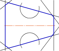
Example of the assembled contour