|
Attaching the Document to BOM and Detaching the Document from BOM |
Scroll |
The following types of documents can be attached to the BOM: drawing(*.cdw), assembly (*.a3d), technological assembly (*.t3d).
|
You can also attach another specification (*.spw) to a BOM objects, as well as the designation and name, will be displayed in the current specification. This technique can be used if you need to supplement an existing BOM that is not editable (it is not possible to delete objects transferred to the current BOM from an attached BOM). |

Connecting a document to BOM
1.If the BOM has not yet been created, create it using the File — Create command.
2.If required, change the BOM style using the Settings... — Parameters — Current BOM — Style command.
3.Run the Assembly Management command  .
.

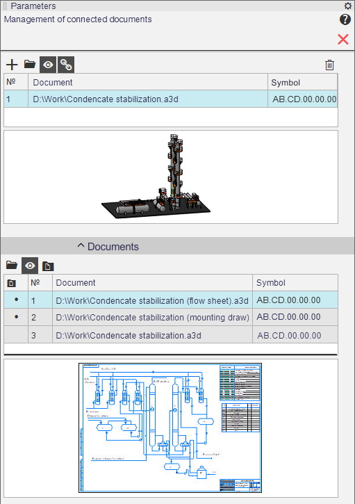
Assembly controls appear on the Parameter Panel, see figure.
4.To attach an assembly or a drawing to the BOM, click Add Document button  .
.
•If you have any open assemblies or drawings, a dialog box will appear where you can select a document. If the required document is not listed, click the Select from Disk button to select it. In the standard file open dialog box that appears, select the folder and file. If you need to specify a BOM, first select the line All files from the list File types.
•If you have any open assemblies or drawings, a document selection dialog will appear where you can select the document. If the desired document is not listed, click Select from Disk to select it. In the standard file open dialog that appears, select the folder and file. If you need to specify a specification, first select All Files from the Files of Type list.
•If there are no open assemblies/drawings, the standard file open dialog will appear.
After specifying the document information about components of this product for which this document is issued, and also about this document and documents attached with it are transferred to the current BOM: the table on the screen is filled (or supplemented) with BOM objects.
|
Assembly Management
5.By default, the Get Properties from Document button  is pressed. This means that the transfer of the values of the Designation and Name properties from the first attached document to the title block of the BOM is enabled.
•To disable the data transfer, de–press the Get Properties from Document button.
•To change the document from which data is transferred,place the required document in the first position of the list using the Move Document Up  and Move Document Down
  buttons.
|
An associative drawing attached to a BOM transfers the designation and name from the assembly projected into it. This means that if the drawing's designation and name are disabled for the assembly and other values for these properties are entered, the BOM created from this drawing will have the designation and name of the assembly, not the drawing. |

7.The Documents section contains a table listing documents that can be added to the BOM's Documentation section: the document itself, as well as documents related to it. Documentation already added to the Documentation section are marked with a dot in the Added to "Documentation" column. Automatic addition occurs for documents whose designation contains a code: SB, VO, etc.
|
A dot in the Added column in the "Documentation" section also marks a document which Designation and Name properties match the designation and name of any specification object in the Documentation section. |
If you need to add any more documents from the list to the Documentation section, select them and click the Add to Documentation  section button More about autmatic adding of documents to the section «Documentation»...
If several documents are connected to a BOM, the set of documents in the Documents section depends on which of the connected documents is selected (in the list at the top of the Parameters Panel).
8.Advanced options:
•you can open any attached document; to do this, select it in the list and click Edit in Window button  ,
,
•you can enable/disable display of contents of the attached documents on the thumbnail; to do this, press/de–press the Enable Viewing of Documents button  .
.
9.When you complete attaching the document to the BOM and configuring the attachment, click Finish  button in the Parameter Panel header.
|
If you want to view the title block of the BOM, activate the detailing display. |
|
By default, information about solids contained in the assembly is not included in the BOM. If this information needs to be reflected in the BOM, change settings for properties of solidsby enabling the Include into BOM option for them. |
Once a document is attached to the BOM, it will be automatically added to the list of BOMs connected to this document.
Detaching the Document from BOM
1.Run the Assembly Management command .
Assembly controls appear on the Parameter Panel, as shown on the figure above.
2.If several documents are attached to the BOM, select the one that should be detached.
3.click Delete button  .
.
Objects corresponding to the component parts of the product for which the disabled document was issued will disappear from the BOM table. Objects corresponding to the disabled document itself or related to it, i.e., those located in the Documentation section, will remain. You can delete them manually if necessary.
4.After you complete detaching the document from the BOM, click Finish button in the Parameter Panel header.
The designation and name in the title block of the BOM may change as a result of detaching the document from it only if the detached document was the first in the list, and the Get Properties from Document button was pressed. In other cases, after detaching the document the title block of the BOM remains unchanged.