|
Establishing splitting a surface into faces |
Scroll |
By default, a ruled surface by two curves is automatically split into faces. At this point, the Auto Determination switch is in the I (on) position. The number of internal edges and the position of their vertexes depend on the design method for ruled surface and view of guiding curves.
•If one of the guiding objects is a point, and the other is a single–segment curve, an edge or a sketch line, and also if both guiding curves are such curves, then the surface will have one face and two terminal edges: starting edge and ending edge.
•If at least one of the guiding curves is a multi-segment curve or chain of curves, then the surface is split into faces using edges; each of these edges originates from the vertex of the guiding curve.
If necessary, splitting the surface into faces can be established. In the example on the picture, one automatically created edge was deleted, and the vertexes of two other edges were aligned with the vertexes of the guiding curve.
|
|
a) |
b) |
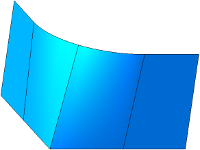
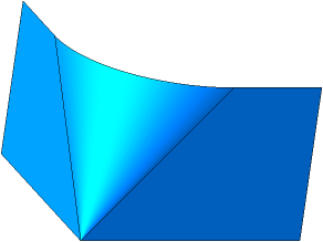
Splitting surface into faces:
a) automatic b) custom
To switch to manual surface splitting, set the Auto determination on-off switch to position 0 (disabled). A field Edge List will appear on the Parameter panel, displaying a numbered list of edges.
You can delete and add edges, as well as move edge vertexes (including terminal vertexes) along the guiding curves, and create or cancel associative links to the vertexes of the guiding curves if required. Please keep in mind the following.
•If one of the guiding curves is a multi-segment curve or a chain of curves, then for building the surface, it is necessary that all the vertexes of this guiding curve are associatively connected with the edges.
•If both guiding curves consist of multiple segments/curves, then to build the surface, it is necessary for the associative link to be applied to all vertexes of one of them.
Controlling the number of edges
Controlling the associativity of edge vertexes
All modifications are applied to the phantom of the surface. If the phantom is not present, it means that the surface cannot exist. It may be caused by the following reasons:
•coincidence or intersection of edges,
•absence of edges protruding from intermediate vertexs of guiding curves.
|
The custom splitting setting is not saved if the user reverts to automatic splitting during the command execution. |

Controlling the number of edges
You can add edges or remove them from the list in the Edges list. To do this, select the required row and click the respective button to the right of the Edge list. For description of buttons, see the table.
Edge control buttons
You can press |
Description |
|
|
Insert edge before current |
The button allows to add an edge before the selected edge in the list. A new edge gets the number of the current edge, and the numbers of subsequent edges are incremented by one. |
|
Insert edge after current |
The button allows to add an edge after the selected edge in the list. A new edge gets the number following the current edge, and the numbers of subsequent edges are increased by one. |
|
Delete |
The button allows to remove an edge from the list. The selected edge is deleted, and the remaining edges are numbered anew. You cannot delete any edges if only two edges are left in the list. |


Controlling the associativity of edge vertexs
By default, the vertexs of edges are associatively linked with the vertexs of the guiding curves. It's available to discard these links and create new links if needed. It's available to link a vertex of the guiding curve or a point built on this line using the commands Point on curve, Point on intersection or Group of points by curve.
To assign an object to be linked with the vertex of an edge, please do the following.
1.Select an edge in the Edges list or in the graphic area.
2.Select the edge vertex by activating the field Starting/Ending Vertex in the group of elements Snap points.
3.If the vertex is linked, please click "X" icon in the Starting/Ending vertex field to delete the link. Then specify the vertex of the guiding curve or the point on the guiding curve to be linked with the specified vertex of the edge. The vertex will be aligned with the specified object, and its name will appear in the Starting/Ending vertex field.
You can arbitrarily move the unlinked vertex along the guide curve by dragging its defining point.
|
If a 3D curve used as the guiding curve is hidden, you cannot snap the edge to the vertex of the guiding curve. |