|
Replacement of faces |
Scroll |
The Replace Faces command serves to replace faces .
.

Step-by-step instructions
1.Form two sets of faces:
•In the graphic area, specify the face (faces) of the solid to be replaced.
The selected face will be highlighted. The name of the face is displayed in the Base objects field on the Parameters toolbar.
•The replaced faces must belong to the same solid or surface. The replacement faces must also belong to the same body/surface - the same as the ones being replaced, or a different one.
Click in the field Replacement objects. Specify a face or a plane in the graphic area that will replace the base objects. The phantom of the modified solid will appear in the graphic area.
When specifying a face, it is possible to select either one of these faces or several that satisfy a certain condition. The elements of the Quick Access Toolbar are used to set the condition.
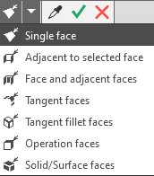
To set the desired set of faces, activate the corresponding field — Base objects or Replacement objects, set the condition for selecting faces and specify the faces.
The selected faces are highlighted, and the phantom of the modified body appears.
2.If there are multiple variants of the operation result, you can view all of them and select the necessary one.
Switching between operation results is done using the Previous Solution  and Next Solution
  buttons. With each clicking of these buttons, a phantom reconstruction occurs in the graphic area.
|
The result selection buttons are not available if a connected set of faces is selected as the replacement object. |

|
|
|
a) |
b) |
c) |
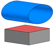
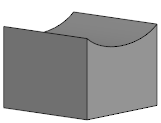
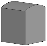
Replacement of a face:
a) replaceable and replacing faces,
b) the operation result — first solution, c) the operation result — second solution
3.If it is required that the result of the operation includes faces offset from the replacements by a specified distance, then enter its value in the Offset field on the Parameter Panel. The counting direction is set using the To object  / After object
  button to the right of the Offset field.
4.If necessary, change the operation name in the Properties section on the Parameter Panel.
5.To complete the operation, click Create Object .
.
The specified face(s) will be replaced, and the corresponding icon will appear in the Construction Tree. .
6.To complete the command, click the Finish  button.
Tips
•The edge offset value can be set in the graphic area — using characteristic point.
•To set the edge offset value, you can use the commands geometrical calculator in the Parameters panel.
•You can assign tolerances to operation parameter values expressed in linear quantities. To do this, select the Tolerance command located in the menu for the desired parameter, or click the icon  , displayed in the parameter field (the icon is displayed if a tolerance is assigned to the parameter value). More about assigning tolerance...
