|
Top down design with the "solid-component" conversion |
Scroll |
|
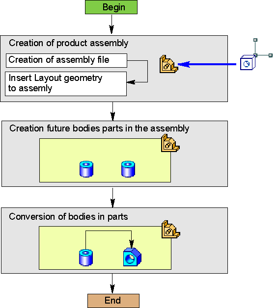
Top-down design scheme with solid-to-component transformation
The method assumes the initial modelling of the assembly using the solids with the subsequent conversion of solids into parts used as assembly components. When creating solids, objects of the layout geometry created beforehand and inserted into the assembly are used.
This method is used in the design of small assemblies, consisting mainly of parts developed for the first time.
Top-down design sequence with solid transformation into components
Step |
Description |
Comment |
|
1.Preparing layout geometry |
•– a part or assembly file with the layout geometry of the developed assembly is created |
||
2.Assembly creation and insertion of the layout geometry |
•file of the developed assembly is created; •pre-arranged layout geometry is inserted in the assembly |
||
3.Building solids within the assembly |
•Solids of the future parts are created within the assembly on layout geometry objects. |
•– objects (planes, surfaces, etc.) are created in the layout geometry; •Solids to be included in different parts shall not be merged using the building operations. |
|
4.Solid to part conversion |
•Solids in the Model Tree are sequentially transformed into parts using the 'Transform to Part' command. |
The option Delete Original in the command is recommended to be left enabled (otherwise, the remaining solids will be considered in the calculation of the CGA model of the assembly). |
