|
4. Bottom up design with pre-layout |
Scroll |
|
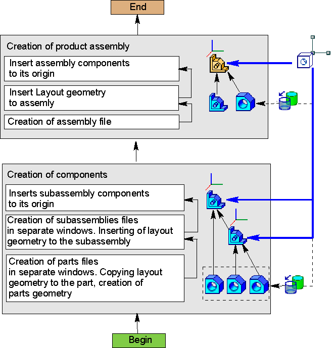
Bottom up design with pre-layout
This method involves step-by-step creation of assembly components and its subassemblies in separate windows starting from the bottom level and to the top level. The required parts of pre-arranged layout geometry are copied in the components. The coordinates of assemblies, subassemblies, and parts match.
This method applies if:
•scope and design of the assembly are clear in the beginning;
•most parts and assemblies are developed for the first time (the amount of borrowed and library models is insignificant);
•there’s no need to simulate moving parts.
Sequence of bottom up design with pre-layout
Step |
Description |
Comment |
|
1.Preparing layout geometry |
•a part or assembly file with the layout geometry of the developed assembly is created |
•if required, collections of geometric objects are created for the main nodes within assemblies |
|
2.Creation of parts |
•parts files are created; •Using the Copy Objects command, the necessary objects and/or their collections required for constructions are copied from the layout geometry file to the detail files. •build operations in part files are executed. |
||
3.Creation of subassemblies, insertion of components in subassemblies |
•subassembly files are created; •layout geometry is inserted in each subassembly; •components are inserted in the subassembly origins; |
•If subassemblies are included in higher level subassemblies, the actions of this step are repeated in higher level subassemblies. |
|
4.Creation of an assembly |
•file of the developed assembly is created; •pre-arranged layout geometry is inserted in the assembly; •components are inserted in the origins |
•inserted layout geometry is used for controlling the developed assembly |
