|
Terms and Definitions |
Scroll |
A B C D E F G H I J K L M N O P Q R S T U V W X Y Z
|
IGES (Initial Graphics Exchange Specification) is a basic specification for graphics exchange. This format is used to exchange geometry between CADs and other vector graphics editors. It is developed and maintained by IGES/PDES, an ANSI-accredited organization. This exchange format is the de facto standard for CAD systems and is supported by virtually all such software products. It is mostly used to exchange 3D models.. |
||||
|
The base bend edge is the flat face of a sheet metal part that contains the bend ege. |
||||
|
An absolute coordinate system is a coordinate system that is automatically created in graphical documents and model documents. You cannot edit or delete a document's absolute coordinate system. |
||||
|
Active view (layer) — a view (layer) whose objects are available for editing and deletion. All objects belonging to the active view (layer) are displayed in the graphics area with their default style (for example, lines retain their thickness, and points retain their style), but in the same color set for that view (layer) in the Document Tree. Several views (layers) of the document can be active at any given time.
|
||||
|
Additional BOM sections are placed at the end of the BOM, after all other sections. Additional sections are typically placed on a new page. Groups of additional sections are called additional BOM sections. More about section blocks... |
||||
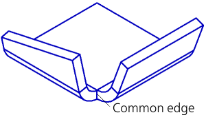
Adjacent bends Adjacent bends have a shared edge, as shown in Figure 1.
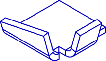
Fig. 1 Bends with corner reliefs, and non-aligned bends are not adjacent. Their corners cannot be closed (Figure 2).
Fig. 2 Flat portions of the sheet part that are modified when the angle is created are called the sides of the closed angle. |
||||
|
Application library — an application designed to extend the standard capabilities of KOMPAS-3D and running within its environment. A typical example of such an application is a library of standard mechanical components, which significantly speeds up the design of assembly drawings. An application library can be created in one of the standard Windows programming environments (Borland C++, Microsoft Visual C++, Borland Pascal, etc.) using the functions of the special KOMPAS-3D SDK application development kit. The library is a dynamically linked library (DLL). By default, library files have the DLL or RTW extensions. KOMPAS-3D It supports simultaneous operation with multiple linked libraries. Library operation modes can vary (window, dialog, menu). After linking the library to the system, the user selects the desired function from its catalog and runs it. |
||||
|
Assembly is a type of 3D model that represents a product manufactured using assembly operations.Assemblies are stored in the Assembly type document with the a3d file extension. |
||||
|
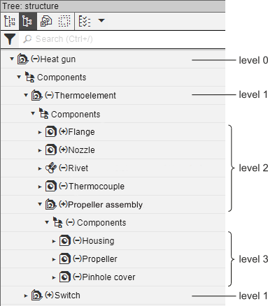
Assembly levels are the nesting levels of the assembly components. The hierarchy of assembly components is represented as the Assembly Tree. The current model itself is located at the topmost (zero) level; this is the root element of the Tree. The remaining objects are located at the subsequent levels. First-level components are those directly inserted into the current assembly. Second-level components are those inserted into a first-level component, and so on.
|
||||
|
Assembly load type is a collection of the assembly component load types. The system load types (Full, Lightweight, Bounding Box, and Empty) are available in any assembly. When a system load type is applied to an assembly, it propagates to all the components. You can create a custom load type for the assembly. It is a combination of different load types for different components; Also, the custom load type includes the “no edit” flag for each component. The assembly load type can be password-protected.More... |
||||
|
Associative hatching (fill) — hatching (fill) whose boundaries coincide with specific line objects (or parts thereof). When the position of these objects changes, the hatching (fill) boundary automatically moves with them. |
||||
|
An associative report is a report that is linked to the document from which it was generated. When objects or their properties are modified, or when the composition of the source document changes, the data in all associated reports is updated accordingly. An associative report is placed within a graphical document. |
||||
|
An associative view is a type of drawing view that is associatively linked to an existing model (part or assembly). When the shape or dimensions of the model change, the view changes accordingly in all associated views. |
||||
Associativity (associative link) Associativity (associative link) — a unidirectional dependence of the position or geometry of one object on the position or geometry of another object. |
||||
|
An attribute is additional non-graphical information associated with one or more objects in a document. This information can take the form of a number, a string of text, or a table with a fixed or variable number of rows. Attribute types (structure descriptions) can be stored either directly within the document or in special files (attribute type libraries). These files have the extension lat. Subsequently, attribute values can be processed by various applications (for example, the Specification Design Module, various calculation programs, etc.). In drawings and fragments, it is also possible to search by attribute values (the Select by Properties command is used for this purpose). |
||||
|
Background view (layer) is a view (layer) whose objects can be referenced for assembly constraints only. These views (layers) cannot be moved, and they are read-only. All objects on background views (layers) are displayed with the same configurable line style. The styles selected for objects when they were created do not apply. A view (layer) is usually made a background view (layer) when it is complete and serves as a «substrate» for adding other objects. Multiple views (layers) in a document can be background views (layers)
|
||||
|
The base point of a 3D object is the point used as the starting point for constructing the object's geometry in the model. The position of an object’s base point is determined automatically by the system and depends on the object type and how it is created. For example, the base point of a component is its absolute coordinate system, while the base point of a sketch-based feature is the center of mass of the curves in that sketch. |
||||
|
Bend is a non-flat portion of a sheet body. There are cylindrical, conical, and transition bends. Cylindrical bends are created with the following commands: •Bend, •Jog, •Sheet body (from an open sketch). The Shell and Ruled Shell commands create cylindrical, conical, and transition bends.More about shells.. |
||||
|
Bend deduction is the BD value in the equation used to calculate the flattened length of the cylindrical part of a bend: l = 2•a-BD. For more information on bend length calculation from bend deduction, refer to... |
||||
Bend direction Bend direction is the direction of the bend relative to the fixed face. The direction towards the fixed face is direct; the opposite direction is reverse. |
||||
|
Bend extension — the part of the sheet body adjacent to the fold on the side opposite the edge along which the fold is located. |
||||
Bend length Bend size — a specified value representing the length of the cylindrical section of the bend. More information on determining the bend deduction length by specifying the bend value... |
||||
Bend line A bend line is a straight line that defines the location of a bend in a sheet. |
||||
Bend offset Bend offset describes the shift of the bend in the plane of the fixed face. A bend is offset perpendicular to the edge along which the bend is positioned. |
||||
|
Bend parameter defines the length of the bend as a flat pattern. The flat pattern length can be calculated from the K-factor, bend allowance, or bend deduction. |
||||
Bend relief Bend reliefs are cuts in a sheet body at the corner of the bend. |
||||
Bend table Bend table — a table containing the values of the bend development parametercorresponding to various material thicknesses, angles, and bend radii. |
||||
|
In KOMPAS-3D, a Bézier curve is defined as a curve consisting of smoothly connected segments described by fourth-order polynomials, each of which is constructed using four control points. The endpoints of these four points are specified by the user, while the intermediate points are calculated based on the condition of continuity of the curve’s derivative and lie on the derivative vector. The user can edit the position of any control point. |
||||
|
Body is a model object that has a certain volume and material. Unlike a component, a body is not stored in a file. A body can consist of one or more disconnected solid regions. A model can contain one or more bodies. |
||||
|
KOMPAS-3D's BOM design module allows you to create BOM documents (with the standard .spw file extension). |
||||
|
A BOM entry is a text in a specification column consisting of several fields. |
||||
BOM name BOM name is the text printed above the components table in the BOM. The BOM name can have multiple lines. The name is user-defined. You can specify different names for the first and subsequent BOM pages (refer to BOM Name of the Drawing). |
||||
|
BOM object represents one or more consecutive BOM rows that define the same physical object. For basic BOM objects, the row cells are auto-filled, sorted within the containing BOM section, linked to a geometry document (e.g., the part drawing), and can have additional properties. Unlike this, auxiliary BOM objects are not auto-filled. Auxiliary BOM objects can be used to add arbitrary text (comments) to the BOM, or to add an empty row in the middle of a BOM section.. |
||||
|
BOM settings control how the BOM data are displayed. The BOM settings include the path to the BOM styles library and a specific style from the library, as well as the mass property settings (unit of measurement and precision). The BOM settings are stored in the document. A single document can contain multiple BOM settings. One of them is current. |
||||
|
BOM style is a collection of BOM settings that control its content and appearance. For the BOM style components, refer to the Style Components section. |
||||
|
BOM subsection is a group of objects within a BOM section. More about BOM subsections... |
||||
|
A bounding box is a hypothetical rectangular prism whose faces are parallel to the coordinate planes and pass through the points on the model objects that are furthest apart. The user can select the types of objects to be included when constructing the bounding box. |
||||
Break direction Break direction is the direction along which the break occurs when a broken view is created. |
||||
|
CALS (Continuous Acquisition and Life cycle Support) — a concept and framework for information support throughout the entire product lifecycle, based on the use of a unified information space (integrated information environment), which ensures consistent methods of interaction among all participants in this cycle: product customers (including government agencies and departments), product suppliers (manufacturers), and maintenance and repair personnel, implemented in the form of international standards that regulate the rules of such interaction primarily through electronic data exchange. |
||||
Center of mass coordinate system Center of mass coordinate system is a coordinate system whose origin is at the model’s center of mass and whose axes are parallel to those of the absolute coordinate system. |
||||
|
Centerline is a graphic object representing centerlines. A distinctive feature of a centerline is that it extends beyond its endpoints by a certain distance. |
||||
|
Centerline symbol is represents two centerlines of axisymmetric objects: circles, ellipses, their arcs, rectangles, and polygons. The line style is Centerline. |
||||
|
Clockwise boundary tracing is used to define the boundary of an area or the axis of an equidistant line by sequentially selecting adjacent segments of intersecting curves. |
||||
|
A collection is a set of model objects required for specific constructions. Collections are used to select objects when creating copies of geometric objects. |
||||
|
A component is a model object represented by another model. Model components can include parts, assemblies, part blanks, local parts, and local part blanks; in assemblies, they can also include standard parts and library elements. A component model can be stored in a separate file or in the current model file. The following components are stored in separate files: •parts, •assemblies, •blank parts, •standard parts, •library models. In this case, the current model does not actually contain the components themselves, but rather references to their files. The current model file contains the following components: •local parts, •local blank parts. These components do not have their own separate files. They are stored directly within the model that contains them. |
||||
Component load types Component load types differ in the amount of data loaded into the RAM. The following system component load types are available: •full: the component is loaded completely; it is displayed in the Design Tree and graphics area •lightweight: the component is loaded so that it is displayed in the Design Tree. In the graphics area, it is displayed without silhouette lines and with reduced accuracy (i.e., less “smooth”) •bounding box: the component is loaded so that it is displayed in the Design Tree. In the graphics area, it is represented by its bounding box •empty: the component is not loaded; it is only displayed in the Design Tree. The lightweight, bounding box, and empty load types improve performance (model rebuilding, rendering after a rotation or translation, etc.) in large assembly models. The user can also enable full loading only for the subassembly they are currently working on, and unload all other components, or, if they need to see their location in the assembly, display only the lightweight or bounding box representation. For subassembly components, both system and custom load types are available. |
||||
|
Composite curve is a curve that consists (or may consist) of multiple sequentially connected segments.A composite curve can be selected and used in operations either as a whole (for this, select it in the Design Tree) or as individual segments (for this, select them on screen).Examples of composite curves: polygon, contour. |
||||
|
Connected curve set (chain of curves) is a collection of curves in which each curve shares at least one vertex with another curve in the set, and each vertex belongs to no more than two curves. |
||||
|
Connected face set is a collection of faces in which each face shares at least one edge with another face in the set, and each edge belongs to no more than two faces. |
||||
|
Connection point is a special object used to define the 3D position of connected (or joined) pipeline components and the orientation of the segment to be attached. The properties of a connection point are its position in the model, the axis that defines the direction of pipeline segment connection at this point, and an additional axis. A pipeline segment can contain multiple connection points. To connect two pipeline segments, connect their connection points and axes (or specify the angles between the axes). |
||||
|
A context menu is a menu that appears when you right-click, containing a set of commands that can be applied to an object or to the document as a whole. |
||||
Context menu panel A context menu panel is a toolbar that appears on the screen next to the cursor after a mouse click (or, in a text document, after selecting a text fragment), containing buttons for accessing the most frequently used commands.. |
||||
|
A contour is a composite object consisting of a chain of curves and constructed from source objects. In a special case, a contour can be represented by a single curve. |
||||
|
A control point is a special model object that allows you to specify the 3D position of a pipeline element along its path. The property of a control point is its position in the model. A pipeline element can contain multiple control points. One of them must be located at a specified point on the path. |
||||
Control segment A control segment is an imaginary line connecting the vertex of the curve being created (or edited) to the previous vertex of the curve. |
||||
|
A copy of geometric objects is a model object that contains geometric objects without history, which are copies of geometric objects from this or another model. A copy may include objects from the model itself, its components, and the assembly geometry it contains. |
||||
Corner angle The corner angle is measured in the projection of the part onto a plane perpendicular to the sides of the angle. Any plane perpendicular to the line of intersection of the outer or inner faces of the sides of the angle may serve as such a plane. |
||||
Corner relief Corner reliefs is a cut applied when creating a new bend near an existing bend, to eliminate material overlap or tearing at their intersection. It may involve partially removing the adjacent bend, its extension, or any bends formed on that extension. The cuts are created along the direction of the new bend, beginning from a plane perpendicular to the adjacent bend line and passing through the intersection point of the tangency lines of the bends’ cylindrical surfaces. |
||||
|
Current BOM style — The BOM style included in the current BOM description. The "current" attribute is assigned to the BOM description in the BOM description management dialog. |
||||
|
Current layer is the layer to which newly created objects are assigned. In a drawing, new objects are assigned to the current layer of the current view, and in a fragment or model, they are assigned to the current layer. Only one view in a drawing, and only one view in a layer (fragment, model) can be current at a given moment. All object creation, editing, and deletion operations apply to the current layer. Any view (layer) can be current. A current view (layer) becomes visible (and foreground in geometry documents). As long as a view (layer) is current, it cannot become hidden or background. After another view (layer) becomes current, the status of the view (layer) that was previously current is restored. For example, once View 1 was current. View 2 was a background view and visible. Then View 2 was made current, as a result of which it became a foreground view. Once View 2 was edited, View 1 was made current again. View 2 became a background view again. |
||||
|
Custom toolbar — a toolbar created by the user during interface customization. You can perform the same actions on custom toolbars as you can on system toolbars. You can rename a user panel |
||||
|
Degenerate face point is a face edge degenerated to a point. |
||||
|
Design tree (Model tree) is a structured list that reflects the composition of the model, the states of its objects, and the relationships between them. The model tree can be represented either as a design sequence—in which case objects are arranged in the tree in the order of their appearance in the model—or as a structure—in which case objects are divided into groups according to their types and sorted within groups in the order of their appearance. |
||||
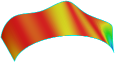
Developable surface Developable surface can be flattened onto a plane without distortion (for example, a cylindrical or conical surface). The Gaussian curvature of such a surface is zero. You can check the curvature of any surface using the comand Check Curvature. For a visual assessment of Gaussian curvature, set the Curvature Map switch to I (On), and select Gaussian in the Method field. A curvature color map is rendered on the selected surface. Blue means the minimum curvature in the current range of curvatures (Figure 1), while red indicates the maximum curvature (Figure 2).
|
||||
Dimension variable Dimension variable is created by the user when adding a dimension in a geometry document or sketch. The value of the variable is the dimension.If it is a driving dimension, the variable can control the dimension value. This is not possible for driven dimensions. |
||||
Document area of the application’s main window Document area in the main window contains document tabs. |
||||
|
KOMPAS-3D applies document formats to geometry and text documents. The sheet format includes the title block and sheet borders. For text documents, the format also includes margins between the text and the border. The formats are stored in system libraries as files with the lyt extension. The user can edit existing formats and create new ones. |
||||
|
Document property — description of the document and the objects it contains. Drawing, fragment, or model documents may have multiple properties. The list of properties is shared for the document and for all objects it contains, but the values of those properties can differ for each object. Properties can be specified: •in geometry documents: the entire drawing or fragment, macroelement, imported view or fragment •in models document: the entire model, component, and body. Associative views in a drawing can access the properties of the parent model.
There are system and auxiliary document properties. System properties are always available resent in the document (such as Item Number, Name, Mass, etc.) Some system properties are filled automatically, while others are user-defined. Auxiliary property stores in an external property library. Auxiliary properties and their values are user-defined. |
||||
|
KOMPAS document template contains format, settings, objects, layers, etc. used to create a new document. Document templates available in KOMPAS-3D out of the box are stored in the \Templates subfolder under the KOMPAS-3D installation folder. You can create custom templates. |
||||
|
The document tree is a structured list of objects that reflects the sequence in which the document was created and its composition. A "+" icon next to an object indicates that it has child objects. To expand the list, click the icon. The context menus for objects in the Document Tree provide easy access to the commands most frequently used when working with objects of a particular type. |
||||
Draft faces Draft faces are flat or cylindrical faces that are angled relative to the reference plane by the Draft operation. There may be multiple draft faces. They can be either adjacent or not. |
||||
|
Drawing is the main 2D geometry document in KOMPAS-3D. A drawing is stored in a binary format file (the file extension is cdw). Each drawing can contain one or more sheets, views, and layers. A drawing uses a sheet format containing the border and title block. It also contains drawing annotations: general notes, and the majority surface finish symbol. |
||||
|
A drawing tree is a structured list that reflects the drawing views and their composition: layers, macroelements, viewport inserts, fragments, and raster images; for associative views, it includes model objects. |
||||
|
A drawing view is an integral part of a KOMPAS-3D drawing; it serves as a "container" for drawing objects, as well as the objects themselves contained within that «container». Objects contained within a single view can form either a single view (a view, section, cross-section, or detail) or multiple views at once. In principle, a drawing can consist of a single view that contains all the necessary views. However, it is strongly recommended to organize all graphical information in the drawing into views, placing each view in a separate viewport. The main characteristics of a view are scale and position. The scale can be selected from a standard range or specified as a ratio of arbitrary numbers. The position of a view is determined by the coordinates of its base point in the absolute coordinate system and the rotation angle. In each view, you can create up to 2,147,483,647 layers for convenient placement and editing of the image. |
||||
|
Duplicates are BOM objects from the same section that contain identical data in the column (-s) used for sorting. More... |
||||
|
DWG — a proprietary binary format owned by Autodesk Inc. (USA). |
||||
|
DXF (Data eXchange Format) — A specialized file format for exchanging information, developed by Autodesk Inc. (USA) for its software products, primarily AutoCAD. This exchange format has become the de facto standard for drafting and graphics systems and is supported by virtually all CAD software developers. |
||||
Dynamic search Dynamic search—automatic recognition of objects currently located under the cursor. The rules for automatic recognition depend on the filters (in the models) and the current process. |
||||
|
Edge is a primitive that represents a section of a face boundary between two vertices that does not contain any other vertices within. In general, selected segments of curves and contours are reported as edges. Special edges: •a closed edge with no vertices (e.g., a circle or ellipse) •zero-length edge degenerated into a vertex (e.g., the vertex of a cone). |
||||
|
An embedded fragment is a fragment created and stored within another—the main—document. The main document can contain any number of local fragment inserts with different scales and rotation angles. Changes made to a local fragment are immediately reflected in all of its instances. Local fragments are convenient to use if the image stored in the fragment is to be used in only one main document. |
||||
|
EMF(Enhanced Metafile Format) is a 32-bit graphics format, It is an enhanced version of the 16-bit WMF (Windows Metafile Format). Developed by Microsoft, the format is used to exchange graphics between Microsoft Windows applications. It supports both vector and raster graphics. |
||||
|
Empty row is a row in a BOM table located immediately above or below a section heading. It separates the section heading from the BOM items. You cannot enter text into an empty row. Empty rows in a BOM are required by drawing standards. |
||||
|
The envelope tree is a structured list of zones created in the document. It contains zones and zone splits. Zones and splits are located at the first level of the tree hierarchy. The second level contains zones resulting from splits. A«+» icon next to an object indicates that it has child objects. To expand their list, click the icon. The context menus for zones and zone divisions in the Tree provide easy access to commands used when working with zones. |
||||
|
Extended text style is additional data stored in the text style that defines the relationship between the number of text lines (one, two, or three), character height and width, and line spacing. |
||||
|
An external model variable is a variable in a model whose value is accessible and can be modified in another model that contains it as a component. The primary purpose of external variables is to control the shape and dimensions of a model both during and after it is inserted into another model. Variables are created and assigned the statuses«external» and «informational» when the model is created. Only a user variable, i.e., a variable in the main section, can be an external variable. An external variable is indicated by the icon An external informational variable is visible but cannot be modified in the model containing the component. |
||||
External variable of the fragment An external fragment variable in a parametric block is a variable within a parametric block whose value can be modified when the block is inserted into another block or drawing (either as an embedded object or via an external reference). The primary purpose of external variables is to control the parameters of a parametric fragment inserted into another document without editing that fragment «from within». An external variable is indicated by the icon If a fragment’s external variable also has the “informational” status, it is visible when the fragment is inserted into another document but cannot be modified. Variables are created and assigned the «external» and «informational» statuses when the fragment is created. Only a user variable, i.e., a variable of the main section, can be an external variable. |
||||
|
A face is a primitive that consists of a portion of a surface bounded by edges and containing no other edges within it. A special case of a face is a closed face that has no boundaries (for example, a spherical or toroidal face). |
||||
Face (plane, surface) normal Face normal is a vector perpendicular to the plane (or tangent plane) at a given point on the face. The normals of a body’s faces are always directed outward. A plane/surface normal can have one of two possible directions. The direction depends on the plane/surface creation sequence and operations used. |
||||
Feature Feature is an object that adds or remove material of a body. There are geometric and auxiliary features.. |
||||
|
Feature dimensions are linear or angular numerical parameters. They can be displayed in the graphics area as dimensions. For example, the numerical parameters of the extrusion feature are the extrusion distance, taper angle, and wall thickness. Feature dimensions are displayed in the graphics area in the following cases: •when the operation is in progress •in a special mode when the dimensions of the selected element are displayed. Feature dimensions can be both driving and driven.More... Feature dimensions can be used in annotations (referenced dimensions). |
||||
|
File Manager — a tool for managing files and folders on a computer. There are file managers built into the operating system; for example, in Windows, this is File Explorer (explorer.exe), but users can also install other programs to work with files and folders. |
||||
Fixed face Fixed face of a bend is the portion of the face that remains stationary. In this portion, the phantom arrow indicating the positive bend angle begins. When the fixed face changes, the position of the arrow changes accordingly. |
||||
|
Flexible subassembly’s components can be moved within the parent assembly. Flexible subassemblies make it easier to position assembly components.More about flexible subassemblies... |
||||
|
Forming tool profile represent the shape of the stamped feature’s bottom. The profile is defined as a sketch. A thin-walled element created by extruding the sketch contains the side walls of the stamped feature. |
||||
|
Fragment is a KOMPAS-3D document (the file extension is frw). It differs from a drawing in that it has no drawing format. A fragment does not have a border, title block, majority surface finish symbol, or general notes. A fragment, like a drawing view, can contain up to 2,147,483,647 layers. A fragment is usually used for images that do not need to be formatted as a drawing (concept designs, etc.) You can also save typical designs as fragments for reuse. Note that in KOMPAS-3D, you can import a fragment file as a link without physically embedding it into the parent document. In this case, when the fragment is edited, the parent document is automatically updated. |
||||
|
A fragment tree is a structured list that reflects the composition of a fragment: layers, macroelements, fragment inserts, and raster images. |
||||
Gap A gap is the distance between the sides of a closed angle. The gap is measured in the projection of the part onto a plane perpendicular to the sides of the angle. Any plane perpendicular to the line of intersection of the outer or inner faces of the angle’s sides can serve as this plane.. |
||||
|
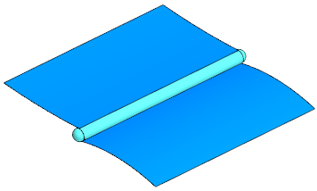
Geometric accuracy refers to the permissible (actual) deviation between objects that are geometrically intended to coincide. For example, the deviation between: •a point on the edge of a body’s face or surface and a curve—the edge of that same face, •the endpoint of a body’s edge and the vertex of that same body, •the endpoints of several edges of a solid and the vertex of that same solid at which these edges should meet. Thus, the position of a vertex can be represented as a sphere with its center at the vertex’s actual (real) position and a diameter equal to the geometric accuracy. The position of an edge can be represented as a «tube» with a diameter equal to the geometric accuracy.
Vertices and edges with geometric precision lower than the default precision in KOMPAS-3D may appear in the model, for example, when surfaces are joined with low precision, or they may result from importing a model from a third-party program. You can check the geometric accuracy of model objects using the Geometry Check command. |
||||
|
A geometric pattern is a type of array of operations in which only the faces and edges of the copied objects are duplicated during creation. |
||||
|
A geometry calculator is a tool for obtaining numerical information about the parameters and relative positions of objects, with the aim of using that information to construct other objects. |
||||
|
Grid is a series of points (or lines) arranged periodically in the graphics area. They facilitate object creation. A grid is a child of a KOMPAS-3D window. The user can hide/show the grid and configure it (color, font, step). Grids are never printed. |
||||
|
A group is a named set of objects in a graphic document. The same object can be part of different groups. |
||||
Handle Handle is a user interface element displayed in the graphics area when you are creating or editing an object. Handles are used to control the object position and shape. |
||||
|
A hidden view (layer) is a view (layer) whose contents are not displayed in the graphics area, regardless of whether it is active or in the background. Thus, a hidden view (layer) is completely inaccessible for any operations.
|
||||
Hierarchy of protected assembly load mode If, at the time a new protected build download mode is created (or when a custom download mode is password-protected), another protected download mode is currently active, the download mode being created (or protected) becomes a child of the current one, and the current one, in turn, becomes the parent of the one being created (or protected). Deleting a subordinate build download mode or its password is only available if the current download mode is the parent. |
||||
|
History-free object lacks information about how it was built, and has no links to other objects. History-free objects may result from deleting the model history or exploding a pattern. History-free objects cannot be edited. In the Design Tree, objects without a history are represented by the following icons:
|
||||
Home page The home page is a feature that provides users with the following capabilities: •opening recently closed documents, •create a new document, •tips on effective work techniques, •links to help and online resources. |
||||
|
IFC (Industry Foundation Classes) is an open product-to-product data exchange format. It was developed by buildingSMART (International Alliance for Interoperability, IAI). The format is used to import models from one system into another. Read-only geometry, properties, and attributes are exchanged. |
||||
|
In-document mode — a mode for viewing and editing specification objects directly within the document (drawing or assembly). To work with specification objects in the document, a special window opens with columns and sections identical to those in the specification. Objects created and edited in subordinate mode are permanently stored in the document. They can be transferred at any time to the bill of materials associated with this document. |
||||
|
An information variable is a variable whose value depends on other variables, dimensions, and the position of objects in the document. An informational variable is indicated by an icon Information variables can be used in expressions. |
||||
ISO 10303 STEP series of standards The ISO 10303 STEP (Standard for the Exchange of Product Model Data) series of standards defines methods for representing product data in a neutral format to enable its exchange and sharing across different information environments. The standards include possible implementations and application protocols. To ensure a consistent description of products across various application domains, information models (referred to in the standard as Application Protocols — APs) are developed based on standard building blocks known as Integrated Resources. An application protocol (AP) describes a specific application domain. The ISO 10303 STEP series of standards underpins the concept and principles of CALS, which has evolved into a distinct field of information technology and is now represented by a series of international ISO standards. |
||||
|
Jog flat region is a part of a sheet body between two bends of a jog.. |
||||
|
The neutral layer coefficient (neutral layer position coefficient) determines the position of the neutral layer along the thickness of a bent body. It is used to determine the lengths of the unclosed sections (when unbending the bends). The length of the neutral layer in a bend does not change when the bend is straightened. As the coefficient increases, the neutral layer shifts toward the outer surface of the bend, and the length of the unfolded section increases. As the coefficient decreases, the opposite changes occur. The value of the k-factor depends on the material’s physical properties, its thickness, and the bend radius. More details... |
||||
|
Layer is a group of document objects. Layers are used to control the visibility, editability, and printability of objects in geometry documents. The maximum number of layers in a document is 2,147,483,647. Each layer can have a unique name for easier identification. A document always has a current layer. All new objects are automatically assigned to the current layer. Objects can be moved between layers. |
||||
|
Layer filter —is a dynamic collection of layers that meet some filter criteria. More... |
||||
Layer group A layer group is a static set of layers grouped by a specific criterion. It is designed to allow you to modify the properties of all layers in the group simultaneously. Learn more about layer property groups... |
||||
Layer Properties Group A layer group is a set of settings for multiple layers. It is designed to allow you to modify layer properties simultaneously while maintaining individual settings for each layer. Learn more about layer groups... |
||||
|
A local coordinate system is a coordinate system that is arbitrarily positioned and oriented relative to an absolute coordinate system. |
||||
|
Macroelement is a composite object treated as a single entity |
||||
Main central coordinate system The main central coordinate system is a coordinate system whose origin coincides with the center of mass of the model and in which the centrifugal moments of inertia are zero. |
||||
Main section of the variable list The main section of variable list consists of a group of document variables created by the user. These variables are located at the top of the Variables Panel, on the first level of the list. You can create a variable in the main section directly within it. When you enter an expression containing variables that do not exist in the document, these variables are automatically created in the main section. |
||||
|
Mate is a relationship between a component and another object in the model that defines their mutual arrangement in 3D. |
||||
Mechanical mate Mechanical mate defines how the objects in the model move relative to each other. Mechanical mates are typically used to simulate how mechanisms work. |
||||
|
Mesh generation is dividing a surface into polygons to create a mesh. To increase the level of detail, each polygon can be further divided into more polygons, which can also be displaced. |
||||
|
Message bar is the panel at the bottom of the Parameters Panel. It shows system messages for the current command or the object under the mouse pointer in the graphics area. |
||||
|
A model version is one of the variants of that model, information about which is contained in a single group document. The system allows for the creation of dependent and independent versions. A dependent version is linked to the original version, while an independent version is not. The set of model variants is graphically represented in the document as a Version Tree. It is displayed on the Versions tab of the Model Tree. |
||||
|
Multi-sheet drawing is a design document containing several sheets that share the same item number and name. The sheets are sequentially numbered. Some features of a multi-sheet drawing: •Default layout for the first sheet of a mechanical engineering drawing — «Mechanical Drawing. First Sheet», and the rest — «Mechanical Drawing. Subsequent Sheets.», •the document reference entered on one page is automatically carried over to the remaining sheets, •By default, continuous numbering is used for pages and items in the technical specifications, •If the "Divide drawing into zones" mode is enabled, the drawing is divided into zones, •regardless of the number of sheets, a drawing may contain only one designation for unspecified roughness and only one set of technical requirements. All sheets of a multi-sheet drawing are saved in a single file *.cdw. |
||||
|
Nested BOM sections are placed within a section, after all the objects in that section. Groups of nested sections are called blocks of nested sections. Learn more about section blocks... |
||||
Neutral plane Neutral plane is a flat face used in the Draft operation to create draft faces. The face selected as the neutral plane must not be parallel to the face to be tapered. The Draft command does not affect the shape, dimensions, and taper angle of the neutral plane. There can only be one neutral plane. |
||||
|
No edit flag — a property of an object that indicates whether editing restrictions have been applied to that object. You can enable or disable editing of an object using the Edit — Disabled or Edit — Enabled commands in the context menu. When working with an object that is available for editing, it can be modified in any available way. Such an object is not marked with any special icon in the Model Tree. When working with an object that is disabled for editing, various restrictions apply, the main ones being the inability to edit it and the inability to delete it from the model. Disabled objects are marked in the Model Tree with a «shield» icon. When working with an assembly, information about the edit restriction on components is recorded in the assembly’s load type and can be saved along with it can be password protected. |
||||
|
Nominal surface is an exact mathematical definition of an object face used in KOMPAS-3D. Faces of Body and Surface type objects have nominal surfaces. Face boundaries (edges) and their positions on the nominal surface are additionally defined. |
||||
|
NURBS curve order is equal to one plus the max degree of the polynomial basis functions that define the NURBS curve segments. |
||||
|
Object coordinate system (CS) is a coordinate system used to define the position or orientation of the object. The CS can be selected when you create or edit the object. The object is always linked to its CS. It moves when the CS moves; it is disabled when the CS is disabled, and it is deleted when the CS is deleted. |
||||
Object selection Object selection is often required before executing a command. For example, to create a 3D feature, you must select its sketch; to create a copy of a graphic object, you must select the original graphic object. The selection colors are specified in the 2D/3D object settings. |
||||
Object selection Object selection is used to perform certain operations. For example, to create a sweep feature, you need to specify the path; to add a parallel segment, you need to specify a straight object to which the segment must be parallel. The selection highlight colors are configured in the 2D/3D editor settings. |
||||
|
An object created in a KOMPAS graphics document using OLE (Object Linking and Embedding) technology. OLE allows you to insert an object created in one Windows application into a document created in another application. The inserted document can be edited using the commands of the application in which it was created.
|
||||
|
Open edge is an edge on the boundary of a face that shows where the body/surface is not fully enclosed. |
||||
OpenGL OpenGL (Open Graphics Library) is a BOM that defines a software interface for applications that use 2D and 3D computer graphics. It includes functions for building complex 3D scenes from basic objects. OpenGL is used in video games, CAD, VR applications, visualization, and research. |
||||
Operation Operation is a way to create or modify an object. |
||||
Operation parameter variable Operation parameter variable is a variable that is auto created when you specify a numerical parameter for an operation. The value of the variable is the numerical parameter.Variables of this type can be used to control the operation parameters. |
||||
|
Operation scope is a set of objects that are modified as a result of the operation. •If the operation adds material, its scope includes the bodies and/or components with which the result of the operation is merged. These bodies and/or components merged with the new feature form a body. •If the operation removes material, its scope includes the bodies and/or components whose volume is reduced. |
||||
|
Parametric mode is when parametric relationships and constraints and auto applied as geometric objects and annotation are created/edited. The type of relationships and constraints is determined online from the sequence of object creation or snap operations. The parametric mode in drawings or fragments can be enabled/disabled at any moment. In the parametric mode settings, you can select the types of relationships and constraints that are applied automatically, and disable the auto-creation of other types of relationships and constraints. You can enable the parametric mode either for all documents you open/create, or for each specific document. |
||||
|
A parent document is a graphic document into which a fragment or view has been inserted via an external link. The content of the insertion is not physically copied into the host document; instead, the host document stores only a reference to the source document of the insertion. Any change to the source will result in an automatic modification of the host document. |
||||
|
Parent view — a parent drawing that contains a view from another drawing. |
||||
|
Parent view is an associative view in a drawing used to create another view. For example, for projection views, the parent view can be the main view, and for a section, it can be the view that contains the cutting plane, etc. |
||||
|
A part is a type of 3D model designed to represent products manufactured without assembly operations. Created and stored in the document «Part», file extension — .m3d. |
||||
|
A part template is a model component that serves as the starting point for building the model. A blank part is used when modeling products that differ only in certain design elements. A part or assembly from a file can be inserted as a part template. The resulting component may or may not retain a link to its source file. In the latter case, the part template is stored in the file of the model into which it is inserted. |
||||
|
A PDM (Product Data Management) system is a system for managing product data. It necessarily includes a document management system (DMS). If a PDM system is used in conjunction with the KOMPAS-3D system, it is used to: •opening and saving files, •selecting a model file when creating Standard and Custom associative views, •selecting a blank model file, •selecting a file when importing a surface, •selecting a component file. |
||||
|
Phantom is an image displayed during certain operations to indicate the current state of the objects being created or edited. For example, if we create a line segment, a phantom representing the future segment is displayed while the user is specifying the second point. When you move the mouse pointer, the phantom is dynamically updated to represent the new position of the future segment. When multiple possible objects exist, several phantoms are displayed at once. One of them is active. The object represented by the active phantom will be created as the user confirms the operation. To make a phantom active, click it. By default, the active phantom is displayed in solid black lines, and other phantoms are displayed in black dotted lines. The color and style of phantoms can be configured in the settings. |
||||
|
Point cloud is a set of points obtained by 3D scanning. It is 3D representation of the scanned object. Each point has its X, Y, and Z coordinates. In most cases, point clouds are not used directly, but first converted into 3D surfaces. For this, a triangulation mesh can be created from the point cloud. The result is a polygonal object. |
||||
|
The point weight is a coefficient that determines the influence of a specific point on a spline curve or spline surface on the configuration of that curve or surface. The geometric meaning of this coefficient is as follows: the greater the point weight, the closer the curve or surface is located to that point (points with a high weight «pull» the spline more strongly than points with a low weight). |
||||
|
Pointer step is the distance the pointer travels after a single press of an arrow key. The pointer step is configurable. The user can set any step. |
||||
|
Polygonal object is a KOMPAS-3D model object that represents raw triangulated or other meshes. This representation is used to precisely define the surfaces of 3D objects with low consumption of computer resources; to import tessellation data from exchange format files, etc. |
||||
|
Primitive — is an elementary component of an object’s geometry. Primitives: edge, vertex, face. |
||||
|
The principal axis of inertia coincides with the corresponding axis of the principal central coordinate system. |
||||
Print device configuration file The print device configuration file is a file with the .pdc extension that contains the current print settings (paper size and feed method, page orientation) and information about the printer. The configuration file is in text format, so it can be opened and edited with any text editor. |
||||
|
A print job is a file with the .pjd extension that contains the sheet numbers and sizes, the names of the documents selected for printing, layout settings for the output area, output parameters, and information about the output device. The job file is in text format, so it can be opened and edited with any text editor. |
||||
|
Proxy object is a representation of an object (face, edge, vertex) that mimics the position of a regular or skeleton component. A proxy object is created when a regular component is replaced by a skeleton component to apply mates within an assembly. It is also created when a skeleton component, with mates applied, is reverted to a regular component. A proxy object mimics the position of the original object when a mate/operation is applied. Proxy objects are created and stored in the assembly. |
||||
|
Reference is text associatively linked to another object containing a text property. The linked object is called the reference source. |
||||
|
Reference to variable is used to assign a value from another document (source) to a variable. Within a model, one version can serve as a reference source for another version. |
||||
|
A report is a graphical table containing data about objects. The objects used to generate a report include models and components of any level, including standard parts, components from model libraries, bodies, as well as graphical macroelements, view inserts, and fragments. Information from a model document or a graphical document is automatically entered into the table. For example, a report may include a list of objects and their properties—name, designation, mass, quantity, position, manufacturer, price, etc. The list of objects and the set of properties included in the report are defined by the user. Properties in the report can be presented as links. An associative report linked to the document from which it was generated can also be created. The report is placed in drawings, fragments, and text documents, and is also saved in *.cdw, *.frw, *.kdw, *.tbl, *.txt, *.ods, *.xls, and *.xlsx formats. |
||||
|
Report style is a collection report generation rules that control its content and appearance. Report styles are stored in the Report Style Library (a *.lrt file). |
||||
|
Report window is invoked by the Create Report command. You can view and edit the data to be included in the report and adjust additional settings for the report. With the Report Window open, you can insert the finalized report into a document, print it, or save it to a file. |
||||
|
Reserved row is a BOM row reserved for adding more content in the future. The differences between a reserved row and other BOM objects are as follows: •you cannot enter text in a reserved row •reserved rows are always at the end of a BOM section •reserved rows have item numbers •you can configure the number of reserved rows in each BOM section, or do not add any reserved rows. |
||||
|
Revision table contains changes to the document. It is not a part of the title block. |
||||
|
Revision table object is one or more consecutive rows of the revision table that represent the same change. |
||||
|
The Text Processor in KOMPAS-3D creates rich text documents (the file extension is kdw). Rich text documents contain text and graphics (drawings and fragments). Like a drawing, a rich text document has a border and title block. |
||||
|
A set of custom toolbars is a collection of toolbars created by the user during the interface customization process. You can perform the same actions on custom sets as you can on system sets. In addition, you can rename custom sets, change their icons, add them to various types of documents, and delete them. |
||||
|
Sheet body — a structure resulting from a surgical procedure Sheet body, Flange or Ruled shell. Other sheet metal operations can be applied to the sheet metal body. |
||||
Sheet format Sheet format includes the sheet outline, border, margins, title block, and revision table. The revision table is optional. Formats are stored in format libraries. The library files have the lyt extension. |
||||
|
SHX-font — AutoCAD's proprietary vector font format. |
||||
|
A silhouette edge is a line along which the normal to the surface is perpendicular to the direction of view |
||||
|
Simplified representation — is a substitute model (part or assembly) that represents a component in an assembly. Simplified representations replace heavy subassemblies in large assemblies to improve performance. A simplified representation contains the minimum possible number of objects to visualize the assembly, position its components, and generate associative views. Only geometry (geometric entities, annotations, and components) is imported from the simplified representation file of the component. Properties such as mass characteristics, name, and item number are imported from the regular component file. |
||||
|
Single-segment curve is a curve that consists of a single segment. A single-segment curve is always selected in its entirety, and any operation applies to the entire curve. Examples of single-segment curves: arc, spiral, and spline. |
||||
|
A skeleton component is a model component created by replacing a component with a skeleton. A layout component has geometry (geometric objects, design elements, components) transferred from the layout file, and properties (mass-centering characteristics, name, designation, etc.) transferred from the source component file. |
||||
|
Skeleton geometry is a part of the model that consists of a set of objects defining the model’s basic geometric parameters (such as fastener locations, assembly space areas, components that define its boundaries, and so on). Components of skeleton geometry can include parts, assemblies, and local parts. |
||||
|
A sketch is a model object created on a plane or a flat face using a drawing and graphics editor. |
||||
Smooth chain of curves A smooth chain of curves is a chain in which the curves share a common tangent at their point of connection. |
||||
|
Snap is used to precisely position objects according to specified conditions (for example, snapping to grid points, control points, or object intersections). |
||||
|
Source view — the source drawing view of the insert, from which an image is inserted into the target view. |
||||
Standard and composite document names Standard document name — contains only the basic part of the name. Composite document name contains the basic part followed by one or more extras: version number, additional version number, or document code. |
||||
|
Standard products (e.g., screws, washers, fittings, etc.) and materials (e.g., C-beams, paper, CAF, etc.) have designations whose structure is defined by GOST and other standards. KOMPAS-3D includes designation templates for such standard components (washers, C-beams, etc.). They are masks with fields to be filled. The template also specifies which fields are used to sort objects of a given type and in what order. When a standard product/material is added to the BOM, some fields of the template may be left blank (for example, if a screw has no coating). For standard products, the Name column of the BOM is auto-populated with a text string containing the filled-in fields of the standard product’s designation. |
||||
Standard mate Standard mate fixes one model object relative to another one. Standard mates are typically used to create an assembly. Standard and mechanical mates can be combined to simulate mechanisms. |
||||
|
STEP AP203 — a format defined by by the ISO-10303 standard (Volume 21) and an application protocol. It is designed for data transfer between various application systems compatible with ISO-10303 STEP. The exchange file is text-based and independent of specific software and platforms. KOMPAS-3D ensures data transfer to the exchange file in accordance with STEP AP203. The exchange file contains data on the model’s geometry, as well as product attributes: Designation, Name, Author, Description, Assembly Structure (tree). Library elements are saved as separate files. The file name of such an element is its name. |
||||
|
Style is a collection of object visualization properties. For example, a point style defines the appearance of the symbol that represents the point, and its color. KOMPAS-3D has styles for lines, points, texts, and hatching. There are default styles available out of the box and custom styles. Styles can be stored either in the document or in external files (style libraries). Line style library files have the lcs extension; hatch style files have the lhs extension; and text style files have the lts extension. |
||||
|
Subassembly is a component of an assembly that is also an assembly. |
||||
Surface A surface is a model object represented by a connected set of faces or by a single face. The faces of a surface cannot be faces of any other objects (such as other surfaces or solids). |
||||
|
SVG (Scalable Vector Graphics) — a scalable vector graphics format designed to describe two-dimensional vector and composite (vector-raster) images. It is based on the XML markup language, so it can be read and edited like plain text. |
||||
|
System menu is displayed as you click the icon in the upper left corner of the window. The system menu contains window size and position commands. |
||||
|
System toolbar — A toolbar created by default in the system. The following actions are available for system toolbars: moving the toolbar, adjusting its size and command set, adding the toolbar to various toolbar sets, and deleting it. |
||||
|
System toolbar collection is available by default. You can rearrange toolbars in the collections, add/remove toolbars, and hide/show the collections. |
||||
|
System view — A view that is automatically generated in every KOMPAS-3D drawing. This view has the number 0 and a scale of 1:1. Its coordinate system coincides with the drawing’s absolute coordinate system. The scale and orientation of the system view cannot be changed. |
||||
Tab Tab is a flat element attached to a sheet body. A tab is created by extruding a closed sketch to an arbitrary depth or to a depth equal to the current thickness of the sheet body. |
||||
|
Text templates are text fragments stored in external *.tdp files. They contain standard texts for quick entry of frequently used text strings. To manage text templates, use the Text Template Library Panel. |
||||
Toolbar A toolbar is a panel that contains buttons for invoking commands. |
||||
Transparency pattern Transparency pattern represents a transparent object by filling the area occupied by the object with pixels. The color of the pixels is the color of the object when its transparency is zero. Pixels are arranged on the screen to form a regular pattern—a grid. «Mesh cells», In other words, the areas where the pixels of a transparent object are absent become larger as the parameter value increases «Transparency» has this object. |
||||
|
Triangulation is a special case of mesh generation when the surface is divided into triangles, and adjacent triangles share a common side. |
||||
|
Triangulation mesh is a discrete representation of the surface of a 3D object as a set of connected triangles. A triangulation mesh completely defines the surface of an object with a given accuracy |
||||
User variable User variable is a variable created by the user. User variables are listed in the main section on the Variables panel. They are not directly linked to object parameters. They are used to access other variables. |
||||
|
Variable pattern table contains variables of the pattern instances. It is stored in the file. The user can assign new variable values to all pattern instances except the seed instance. Variable pattern tables are not available for mirror patterns and pattern-driven patterns. |
||||
|
Variables table contains external variables. It is store in the document file. A Variables table is used when a file is imported into another document. The external variables of the parent document are assigned the values of the imported file’s variables. The Variables table is user-defined. The Variables table can be exported to/imported from Excel files. |
||||
|
The version tree is a structured list of model versions contained in the document. It contains dependent and independent instances. All independent instances are located at the first level of the tree hierarchy. Dependent instances are hierarchically subordinate to the instance that serves as their source. The context menus for instances in the Tree provide easy access to commands used when working with instances. |
||||
|
A vertex is a primitive that represents the end of an edge. In general, vertices are defined as coordinate origins, points (including those in sketches), control points, and connection points. A special case of a vertex is an edge of zero length (for example, the vertex of a cone). |
||||
|
View annotation — is an object in an associative drawing view that contains a dimension, item number, note, or table imported from the 3D model. |
||||
View label View label is a text object, a part of a drawing view. The view label text is auto-generated and updated. A view label includes: •alphanumerical view name •the «Flattened» Pattern symbol •view scale •the «Rotated» symbol •angle of rotation •sheet number •grid reference.
The user can enable/disable any of the view label elements listed above in the view settings. All elements of the view label are references.
|
||||
|
A virtual part is a model component stored within that model. A part or assembly from a file can be inserted as a local part. Additionally, a local part can be created while working with the model. |
||||
|
Visible view (layer) — a view (layer) whose contents are displayed in the graphics area. Active views (layers) are displayed in their selected colors, while background views are displayed in the specified style. |
||||
|
VRML (Virtual Realit Modeling Language) — a standard file format for displaying interactive 3D vector graphics. It is designed to describe 3D images and works with objects that define geometric shapes and their spatial relationships. The description of VRML objects is stored in a text file with the extension wrl. |
||||
|
A zone is a defined area within the model space. It is used to select objects that are inside or outside this area, or that intersect with it. |