|
Mark/reference symbol |
Scroll |
In KOMPAS-3D, you can create the following types of marks:
•Mark/reference designation without leader,
•mark/reference designation with leader,
•mark/reference designation on line.
For precise cursor positioning and parameter setting during construction, you can use Snaps and geometrical calculator.
Mark/reference symbol without a leader
To create a mark/reference symbol without leader, do the following actions.
1.Invoke the Mark/reference symbol without leader command.
In the graphic area, a phantom of a bounding rectangle of designation will appear.

2.Set the position of mark/reference symbol.
3.If it is required to rotate symbol, enter the value of rotation angle into the Angle field on the Parameter Panel.
4.Enter the text of mark/reference symbol. To that end, click in the Text field on the Parameter Panel or in a text box on the phantom of symbol, or press any of the alphanumeric keys on the keyboard. The Add Text subprocess will be started. In the graphic region, a table for input of symbol text will appear. Details...
|
The context menu of the Text field contains all the marks created in the document. To create a mark with already existing text symbol, select it from this menu. With the Auto-numbering option enabled (see below), a running number will be assigned to it. |

5.To automate assignment of free numbers to elements during input of text, enable the Auto-numbering option. Details...
6.If necessary, enter the text into the Comments field. In this field, you can enter any information, for example, on the element for which a mark/reference symbol is created. The comment in the drawing is not displayed.
7.Set up the Mark Parameters.
8.To complete creation of the symbol, press the Create Object  .
.
9.To complete operation of the command, click the Finish  .
.
|
|
a) |
b) |
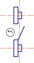
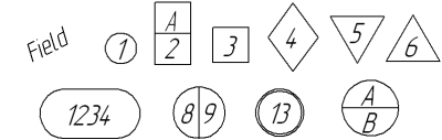
Mark/reference symbol without leader
a) example of use, b) types of symbol form
Mark/reference symbol with leader
To create a mark/reference symbol with a leader line, use the Mark/reference symbol with leader  command.
Step-by-step instructions
1.Set a point to which the first branch of the leader line points.
After indication of this point, a symbol phantom will appear in the graphic area.
2.Specify the starting point for the landing.
3.Enter the text of mark/reference symbol. To that end, click in the Text field on the Parameter Panel or in a text box on the phantom of symbol, or press any of the alphanumeric keys on the keyboard. The Add Text subprocess will be started. In the graphic region, a table for input of mark text will appear. Details...
|
The context menu of the Text field contains all the marks created in the document. To create a mark with already existing text symbol, select it from this menu. With the Auto-numbering option enabled (see below), a running number will be assigned to it. |
4.To automate assignment of free numbers to elements during input of text, enable the Auto-numbering option. Details...
5.If necessary, enter the text into the Comments field. In this field, you can enter any information, for example, on the element for which a mark/reference symbol is created. The comment in the drawing is not displayed.
6.Set the parameters of mark/reference symbol. Details...
7.Create the necessary number of branches of the leader. Details...
8.To complete creation of the symbol, press the Create Object button.
9.To complete operation of the command, click the Finish .
|
|
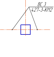
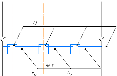
Examples of mark/reference symbol with the leader line
To create a mark/reference symbol on the line, do the following actions.
1.Run the Mark/reference symbol on the line  command.
After invoking the command, the cursor will take the shape of a square "trap".
|
The size of the cursor’s trap can be changed in the dialog for setting up the cursor. |
2.Indicate the object to place a mark (the outline of a part, the leader line of a dimension, etc.). Its name will appear in the Object field on the Parameter Panel. In the graphic region, a symbol phantom will appear.
3.Enter the text of mark/reference symbol. To that end, click in the Text field on the Parameter Panel, or press any of the alphanumeric keys on the keyboard. The Add Text subprocess will be started. In the graphic region, a table for input of symbol text will appear. Details...
|
The context menu of the Text field contains all the marks created in the document. To create a mark with already existing text symbol, select it from this menu. With the Auto-numbering option enabled (see below), a running number will be assigned to it. |
4.To automate assignment of free numbers to elements during input of text, enable the Auto-numbering option. Details...
5.If necessary, enter the text into the Comments field. In this field, you can enter any information, for example, on the element for which a mark/reference symbol is created. The comment in the drawing is not displayed.
6.Select the placement of mark by pressing the required button in the Location group:
 Above Line,
 Below line,
 In Line Break.
The position of mark can also be changed by moving the cursor. At the same time, switching between the options of placement of mark is performed.
7.Specify the point determining the position of mark on the selected object. After that, creation of symbol automatically ends.
If the point is specified outside an object, then the position of mark is determined by a projection of the set point onto the object or its continuation. In this case, the object (except arcs of ellipses, NURBS, conic curves, and Bezier curves) automatically extend to the required distance with a thin line.
8.To complete operation of the command, click the Complete .
|
|
a) |
b) |
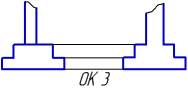

Mark/reference symbol on line
a) an example of usage, b) options of text placement
|
Distances from text to the line are set in the section Symbols for civil engineering — Mark/reference symbol — On the line — Parameters of the dialog for setting up the current document. |

