|
The guiding line of the lofted element |
Scroll |
If necessary, you can select a guiding line – a contour that defines the direction of the construction of the element through sections. A guiding line can be a spatial curve, sketch, or edge.
The figure shows examples of elements built on the same sections with and without the use of a guiding line.
|
|
|
|
a) |
b) |
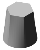
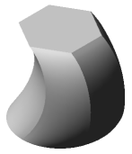
Lofted elements: a) without a guiding line; b) with a guiding line
To select an existing object as the orienting line, click in the field Guiding Line. Select the desired object in the Design Tree or in the graphics area. The name of the selected object will appear in the Guiding Line field.
|
When constructing a lofted element, it is impossible to simultaneously use a guiding line and guiding curves. Since guiding curves have a higher priority, the guiding line is ignored. |

Requirements for the guiding line
•The lofted element can have only one guiding line.
•The guiding line can be open or closed.
•The guiding line should intersect the plane of the extreme sections.
•The tangent to the guiding line at its common point with the sketch plane should not lie in this plane.
•If the guiding line is multi-segment (for example, a contour consisting of several curves), then its segments should be joined tangentially or smoothly.
|
If the guiding line is closed, then only a closed element can be built and vice versa. |