|
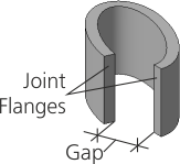
Joint Flanges and Gap |
Scroll |
Parameters of the joint flanges and the gap are set in the Borders section. It is available for shell rings based on closed sketches.
|
Joint flanges of the shell ring
Select a method for creating joint flanges using the Joint Flanges group of buttons. The following options are available.
 Perpendicular to the sheet surface: the edge surface is perpendicular to the surface of the shell ring along the entire gap.
When the gap is placed on a flat portion, the joint edges are flat (Fig. a). On a non-flat portion, the joint edges can be both flat (Fig. b) and ruled (Fig. c).
 Parallel to each other: the edges are trimmed by planes parallel to the planes, which in turn are perpendicular to the contour of the flange at the point of the gap.
|
|
|
a) |
b) |
c) |
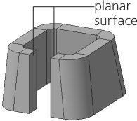
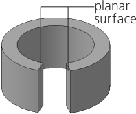
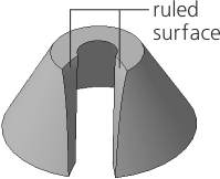
Construction of joint edges by method Perpendicular to sheet surface
|
A shell ring with an open sketch (sketches) has joint flanges always perpendicular to the sheet surface. |

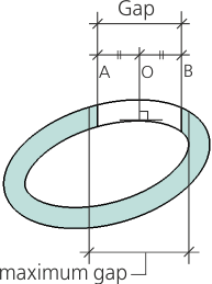
A gap value is set in the Gap field. Only positive values are allowed. The maximum admissible value of the gap depends on its location in the shell ring: the gap should not go beyond the inner wall (see Figure).
|
Construction of joint flanges using the Parallel to Each Other method