|
Capping Methods |
Scroll |
To select the required method of corner capping, use the Capping method button group (see Table).
Corner capping method
Capping method |
Result of plotting |
||
|
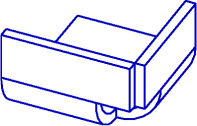
Butt capping |
|
|
|
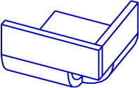
Capping with overlay |
|
|
|
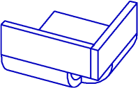
Tight Capping |
|
|


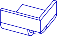
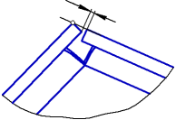
When you select the Capping with Overlay option, the arrow on the phantom shows the side of the corner which will overlap the second side.
To change the overlapping side, press the Switch Side  button to the right of the Gap field. The position of the arrow in the graphics area will change. You can also change the overlapping side using the defining point.
Principles of Butt Capping and Tight Capping
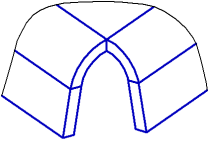
Consider a principle of butt capping and tight capping on the example of the part shown in Figure.
|
|
a) |
b) |
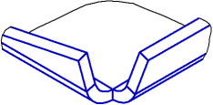
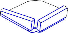
Butt capping
a) initial part state, b) operation result (gap is not zero)
The procedure to define the sides of the corner for capping is given in the Table.
Defining the position of corner sides with butt capping and tight capping
Design pitch |
Result |
|
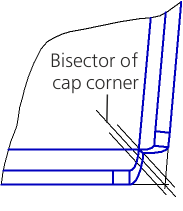
1.A bisector of the capped corner is built in the plane of gap measurement. |
|
|
2.The sides of the corner are extended until they contact with the created lines. |
|
|
With tight capping, the sides of the corner are additionally modified: their side faces become parallel to the bisector. |
|
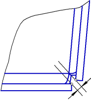
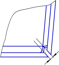
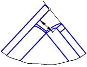
The minimum gap value is 0; the maximum value is defined as shown in Figure.
|
Maximum gap in butt capping
Principle of Capping with Overlay
Capping with overlay can be built in different ways depending on the type of the corner to be capped – acute or obtuse. The relative position of the bends (the angle between the bend lines), as well as angles of bends themselves have impact on the value of the corner to be capped.
Consider a principle of capping with overlay on the example of the parts shown in Figure.
|
|
a) |
|
|
|
b) |
|
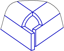

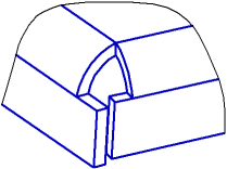
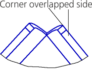
Capping with overlay (original part and operation result)
a) capped corner is acute, b) capped corner is obtuse
Capping with overlay is described in the Table below.
Capping with overlay
Design pitch |
Result |
||
Capped corner is acute |
Capped corner is obtuse |
||
1.A line is built in the plane of gap measurement – a trace of the plane of the outer face of the corner overlapped side. |
|
|
|
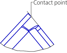
2.The overlapping side extends until it contacts with this line. |
|
|
|
3.The overlapped side extends until the distance between it and the overlapping side equals the specified gap value. |
|
|
|


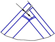
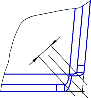
The minimum gap value is 0; the maximum value is defined as shown in Figure.
|
|
a) |
b) |
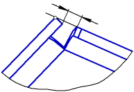
Maximum gap in capping with overlay
a) capped corner is acute, b) capped corner is obtuse