|
Corner treatment |
Scroll |
To select a method of corner treatment, use the Corner Treatment group of buttons.
Corner treatment methods with various capping methods are given in the Table.
Corner treatment options for various capping methods
|
|
|
||
|
No Processing |
|
|
|
|
Circular |
|
— |
|
|
Juncture by border |
|
— |
|
|
Juncture by chord |
|
|
|


Options Circular, Juncture by border and Juncture by chord are available if adjacent bends have the same angles and the same radii. Joint by chord is available in all capping methods, while joint by flange and circular treatment are available only for butt capping and tight capping.
If you use Tight Capping with the Juncture by border or Circular corner treatment, overlay of flat patterns of adjacent bends might occur if the gap is zero or small. In this case, it is recommended to pick such gap value which will exclude overlay.
Circular of an angle represents the processing of an angle by the method of Juncture by border with the addition of a circular hole. With a circular corner treatment, you should set advanced options (see below).
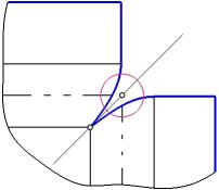
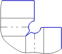
Parameters of Circular Corner Treatment
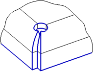
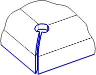
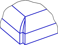
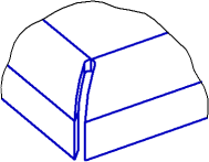
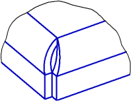
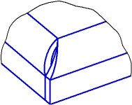
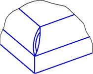
The hole center is located on the line that passes through the angle point and the intersection point of bend lines. The procedure of corner capping with circular treatment is shown in Figure.
|
|
|
a) |
b) |
c) |
Corner capping with circular treatment
a) corner capping with juncture by border;
b) hole placement; c) construction result
Set the hole parameters.
•Select a method of hole placement by clicking the required button in the Location group (see Table).
•Set the hole diameter in the Diameter field.
•In the Move field, set the hole offset along the line containing its center. With a positive value, the hole is shifted to the angle point, with a negative value – to the intersection point of bend lines.
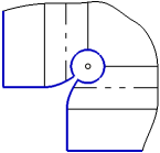
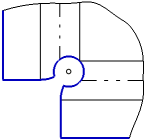
Hole placement method
Placement method |
Hole placement rules |
Result of plotting |
|
|
At intersection of bends |
The hole center is located at the intersection of bend lines. |
|
|
At Angle Point |
The hole center is located at the angle point. |
|
|
Through Angle Point |
The hole passes through the angle point. |
|


|
Corner capping with circular treatment is not possible if: •the hole with the current diameter value splits the sheet solid into separate portions, •the hole with the current parameters (diameter and offset) do not have intersections with cylindrical faces of bends. |

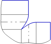
Preservation of angle circular treatment during simplification of the flay pattern contour
To position the drilling tool, you can use the lines of circular corner treatment on the simplified flat pattern contour. For this purpose, the Save on simplification option is used. When the option is activated, a hole will remain on the simplified contour, obtained as a result of circular treatment. When this option is disabled, the contour simplification is performed with complete removal of circular treatment lines.
The option is present on the Parameter Panel in the following cases:
•using the command Cap corners, if the toggle switch Uniform parameters is in the I position (enabled),
•in the commandsBend and Bend by Sketch when capping adjacent angles,
•using the commandConvert to sheet part, if the Unified/Individual toggle switch in the Bend parameters group and in the Angle parameters are in the Unified position.