|
Cap corners |
Scroll |
Corner capping is such a modification of bends and/or their extensions to make them match each other flush or with the given gap, without creating intersections.
Corner capping is available when building a bend by multiple edges in the Bend and Bend by Sketch.
The corner capping parameters are configured in the Cap corners section.
The following capping types are available:
•Cap adjacent corners allows to configure corner capping at the joints of chain edges.
•Cap in the start and Cap in the end allow to set the treatment parameters for the initial and final flanges of the bend.
This option is available in the Bend command if at least two edges among the edges specified for construction are joined by vertex or bend.
This option is available in the Bend by Sketch command if the bend is built along the chain of edges.
|
|
|
|
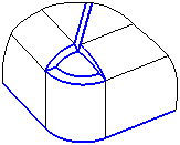
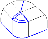
a) |
b) |
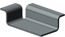

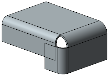
Examples of bends along the edge chain:
a) without corner capping, b) with capping (one of available variant)
To configure corner capping, do the following.
1.Set the Cap adjacent corners toggle switch to I (enabled). The controls to configure capping will appear on the Parameters toolbar.
2.Set the capping parameters.
•Select the capping method by clicking the required button in the Method group; it is specified in the same way as when running the Cap corners command, with just one exception: the capping method With Overlay is not available. Details...
•Select a method for corner treatment by clicking the required button in the Corner Treatment group. Details...
•Enter a gap value in the Gap field. Details...
The table (see below) lists corner treatment options for various capping methods when constructing a bend along a chain of edges joined by bends.
The images show a bend along a chain of edges with angle different than 90°. If the bend angle along a chain of edges joined by bends is 90°, the selected capping method has no influence to the capping result. The corner between such bends is always butt capped.
Corner treatment options for various capping methods
Bend along the chain of edges joined by bends
|
|
||
|
No Processing |
|
|
|
Circular, |
|
|
|
Joint by flange, |
||
|
Juncture by chord |


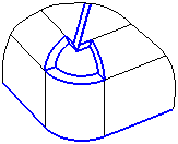


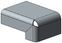
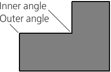
Note the following features when building a bend with capping along the chain of edges joint by vertices. In the event the chain includes edges that form an inner face angle (see Figure), you can cap using any method of corner treatment apart from the No Processing method. In the Bend by Sketch command, capping of the inner corner less than 90° is possible if the first element in the bend sketch is an arc. If the first element of the sketch is a segment, capping is not possible.
|
|
Inner and outer angles of the sheet solid face |
Sketch starting from an arc |

Capping in the Start and Capping in the End
The option is available in the Bend command if the bend is built by an open chain of edges and/or separate edges.
This option is available in the Bend by Sketch command if the bend is built along one edge or an open chain of edges.
The Cap in the Start and Cap in the End switches allow to shape the initial and final flanges of the bend in such a way that is required for capping with the assumed adjacent bend (for example, for further joint with another part). Since adjacent bends for the initial and final flanges are missing, capping is performed relative to the plane α that passes through the end point of the bend A (Fig. a).
|
|
a) |
b) |
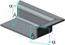

Bend with closing at the beginning and at the end.
a) point A and plane α, b) top view, offset and angle
To configure capping in the start and/or end, do the following.
1.Set the relevant toggle switch to I (enabled). The controls to configure capping will appear on the Parameters toolbar.
2.Set the position of the plane α. To do this, in the Angle field enter a value of the angle between it and the plane perpendicular to the bend line. The angle value can be both positive and negative.
3.Set the capping parameters:
•select the capping method, by clicking the required button in the Method group; it is set similarly to performing the Cap corners command, with the only difference being: the Overlap Closure method is absent,
•select the angle processing method, by clicking the required button in the Corner Treatment,
•when necessary, in the Gap field, enter the distance at which the bend edge should be positioned from the α plane (see Fig. b); a zero offset means that the bend edge will be located in the α plane.
|
A bend by sketch cannot be built if a negative angle is specified for capping in the start or in the end, and the No Processing method is selected for corner treatment. |
