|
Contour |
Scroll |
Use the Create Contour command  to build a contour consisting of parts of intersecting geometric objects.

Step-by-step instructions
1.Specify the geometric object (or its part) with which you want to start traversing the contour. A phantom of the first contour section appears on the graphics area (on top of the original object).
2.To set the remaining sections, click on the desired objects. Phantoms of new contour sections will appear in the graphics area.
Each next specified object must have a common point with the extreme section of the contour being created.
|
The selection of any of the extreme sections of the contour can be canceled by clicking on it with the mouse. Sections within the contour are not available for cancellation (they are displayed in a different color). |

3.To fix the contour in the document, click Create item  button.
4.To complete operation of the command, click Finish  .
.
|
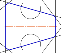
Example of the assembled contour
Additional features when building
•Changing the order of traversal of non-branching nodes – nodes in which the direction of further movement is only one.
By default, such nodes are processed automatically, i.e. when specifying an object, this object itself and the neighboring objects/chains of objects connected by non-branching nodes are selected. With this, the Method of passing nonbranching nodes toggle switch is set to Automatically.
If you need to manually specify each section of the circuit, set this toggle switch to Manually.
•Deleting source objects after contour creation.
To perform a deletion, enable the option Delete source objects.
•Select the style of drawing contour lines.
To select a style, expand the list Style and specify in it the required line. More details on selecting line style...