|
Isolation mode |
Scroll |
How to enable the mode
To enable the isolation mode, the following methods are used:
•Call Isolate objects  . The command is available if at least one component, mating, array, copy of geometric objects, detailing geometry, etc. is selected. You can also isolate solids and surfaces, both created in the model and belonging to its components.
To select a component, specify it in the Design Tree or select any object belonging to it in the graphic area.

•Enable the Isolate option when executing the Select — Select nearestcommand. The command allows for selecting assembly components based on their proximity to an already specified component and, if necessary, isolating them.
After enabling the mode, the selected components will remain visible in the graphic area, and the other objects will no longer be displayed. The isolation mode icon  will appear in the model graphics area.
When switching to the isolation mode, keep in mind the following:
•if the command was run for a subassembly, the entire subassembly is isolated;
if the command was run after selecting separate components of the subassembly, only the selected components are isolated,
•if the command was called for a mating, components involved in this mating are isolated,
if the selected object is not an operation (sketch, plane, etc.), the isolation command is available provided that the object belongs to a component, and isolates this component,
•if a primitive (face, edge, vertex) was selected in the graphic area when the command was called, the object (component or solid/surface belonging to the model itself) comprising the selected primitive is isolated.
The drawings show the selection of isolated components and the result of the Isolate Objects command.
|
|
a) |
b) |
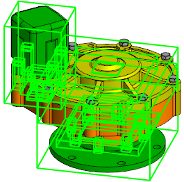
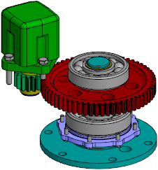
Enabling the isolation mode using the Isolate Objects command:
a) selecting objects for isolation, b) result
Notes on the mode operation
In the isolation mode you can work with isolated components, perform any operations such as building objects, measurement, etc.
In the Design Tree, names and icons of isolated components are black, those of hidden components are grey. When you select a hidden component in the Design Tree, its bounding box is displayed in the graphic area.
In the object rows in the Construction Tree during the isolation mode, the icons Visible and Hidden are not displayed. To control the visibility of components, use the Add to Isolated and Remove from Isolation commands in the component's context menu in the Tree. After calling one of these commands for a component, the other command appears in its context menu.
To display a hidden component, select it in the Design Tree and call the Add to Isolated command from the context menu.
To hide a component, select it in the Tree and call the Remove from isolation command from its context menu.
|
To add a separate solid or surface to isolated/exclude them from isolation, enable displaying model structure, select the required body/surface in the Design Tree and invoke the Add to Isolated or Remove from Isolation commandfrom the context menu. |

Note that in the isolation mode the value of the property Visibility set for the model objects does not change. If a hidden component was selected for isolation, then after switching to the isolation mode it does not become visible. To enable the display of such a component, invoke the Show command from the component context menu in the Design Tree.
Closing the mode
To complete your work in the isolation mode, do one of the following actions:
•Click Isolate Objects on the Quick Access toolbar,
•click the mode icon in the graphic area,
•call the Isolate Objects command from the View menu.
After you exit the isolation mode, visibility of objects is restored.
Changes made while working in this mode are saved after you exit it.