|
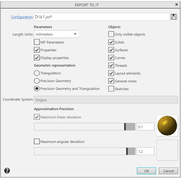
Parameters of writing to JT format dialog |
Scroll |
This dialog appears on the screen after pressing the Parameters button in the dialog Auto Export Models.
The dialog allows you to set up the export options.

Description of Controls
The element |
Description |
|
Configuration |
Click the link to load the configuration. Configuration name is displayed in the field to the right. Configuration is a special file with a list of export parameters. If a configuration is loaded, it is automatically applied to export of a current document, and also to other export procedures in the current KOMPAS-3D session. |
|
|
By Default |
To load the default export setting, click this button. |
|
Save to file |
Press this button to save the settings configured in this dialog to a configuration file. A configuration file for export to JT format has the extension jxcf . |
Group Parameters |
||
Length Units |
This list allows you to select a unit of length for writing coordinates of vertices and normal vectors of triangular faces. |
|
MP Parameters |
This option manages the export of CMP parameters. If this option is enabled, the density and mass values specified in the model will be exported. |
|
Properties |
This option allows to enable or disable export of all properties except density and mass. The KOMPAS-3D model properties are transformed into attributes when saved to JT document. |
|
Display properties |
The option allows you to enable/disable the export of colors of body and surface edges. If the assembly contains inserts of the same component differing only in color, then enabling the transfer of display properties will result in the creation of duplicate components, which will also differ from each other only in color. If this is undesirable, disable the transfer of display properties. In this case, the colors will not be transferred, but duplicate components will not appear either. |
|
Geometric representation |
This group of options allows you to select the method of saving the model geometry. |
|
Triangulation |
Surfaces existing in the model are transmitted in approximated form – multi-faceted surfaces with triangular faces. |
|
Precision Geometry |
Existing surfaces in the model are transmitted in the format of an exact boundary description (Boundary Representation, B-Rep). |
|
Precision Geometry and Triangulation |
When writing, both versions of the representation are transferred – exact geometry and triangulation. |
|
Group Objects |
This group of options is used to manage the export of model objects. If the Only visible objects option is enabled, only visible model objects are exported; if it is disabled, all objects, both visible and hidden, are exported. The remaining options control the export of the following objects: •solids, •surfaces, •curves, •threads, •detailing elements — dimensions, designations, captions and tables, •technical specifications; •sketches. |
|
Coordinate System |
This list is used to select the coordinate system to write 3D models in JT format. It is available if there are several coordinate systems in the model. If there is only one coordinate system, the model is written in the absolute coordinate system. |
|
Approximation Precision |
This group of options is used to set the approximation parameters. Present in the dialog when the Triangulation option is enabled, or Exact geometry and triangulation in the Geometric representation group. |
|
Maximum linear deviation |
Enabling this option allows you to set the maximum permissible deviation along the normal of the triangular face of the transmitted surface from the original surface. The deviation can be set using the "slider". To change the amount of deviation, move the slider on a scale between the positions of the extreme left ("rough") and the extreme right ("fine"). The range of valid values is 0,001–1 mm. The desired value can be also entered manually in the field to the right of the scale. In this case, the maximum allowable value is 30 mm. |
|
Maximum angular deviation |
Enabling this option allows you to set the maximum allowable angle between the normals of adjacent triangular faces of the transmitted surface. The deviation can be set using the "slider". The range of permissible values of angular deviations is 45–0.1 (in degrees). The desired value can be also entered manually in the field to the right of the scale. In this case, the maximum allowable value is 90. |
|


Click OK after parametrization. To exit the dialog without changing the export parameters, click the Cancel button.