|
Overview |
Scroll |
In the design process, you may need to divide a solid existing in the model into multiple solids. To that end, the Cut  .
.
See figures for solid cutting examples. You can see the source solid on the first figure and the solids resulting from cutting the source solid with constructive planes on the second figure.
|
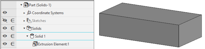
Source solid
|
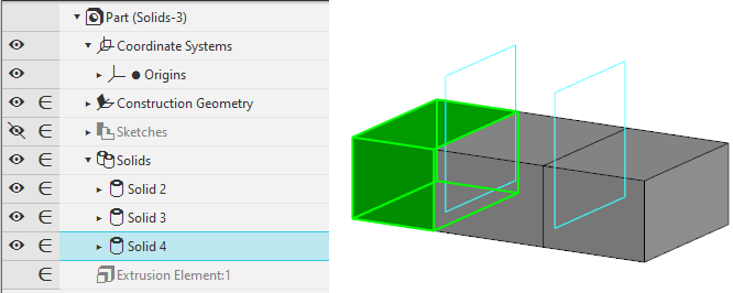
Resulting solids
After cutting, the source solid is deleted from the model. The resulting solids inherit properties of the source solid, including the following:
•parameters for CMP calculation;
•color, optical properties and textures applied to the entire solid;
•Include into BOM attribute.
You can later change properties for each solid individually.
If necessary, you can cut not only a solid built in the current model, but also a solid included in a component. In this case, the solid you cut is moved to the assembly that contains the component and is then divided into multiple solids. Solid properties are not copied from the component model to the assembly; this is why the resulting solids have default property values.
You can manage the set of solids created by cutting. You can select the solids to keep in the model and the solids to delete. You can do this in the process Modifying a Set of Solids. Details...
See Also