|
Methods of building attachment points |
Scroll |

For building of the attachment point indicate the object, the parameters of which allow uniquely determine the position and orientation of the point. The name of the selected object is displayed in the Object field on the Parameter Panel. An associative connection is formed between the attachment point and the object.
The table shows the objects available for designation and the results of building a point, due to the choice of the object.
Object |
Rules for determining the parameters of the connecting point |
|
Sketch |
•The point coincides with the origin of the sketch coordinate system. •The first axis is perpendicular to the sketch plane. The second axis is the same as the y-axis of the sketch coordinate system. |
|
Intermediate vertex of the broken line |
•The point coincides with the top of the broken line. •The first axis is parallel to the principal normal to the plane passing through the previous and subsequent segments of the broken line. The second axis is parallel to the projection of the next segment of the broken line to the plane perpendicular to the previous segment. |
|
Point created using On Curve |
•Connecting point coincides with the specified point. •The first axis is parallel to the binormal to the curve at the point. The second axis is parallel to the principal normal to the curve at a point. |
|
|
To create a connecting point it is impossible to use a point built on a linear curve. |
|
The point created using the On Surface method or the Projection point |
•Connecting point coincides with the specified point. •The first axis is parallel to the principal surface normal at a point. The second axis is parallel to the tangent in direction V. |
|
Circular or elliptical arc (curve, contour in sketch, or edge) |
•The point coincides with the center of the arc. •The first axis is perpendicular to the plane of an arc. The second axis in the arc plane is perpendicular to the radius drawn to the initial vertex. |
|
Coordinate System |
•The point coincides with the origin of the coordinate system. •The first axis coincides with the Z axis of the coordinate system. The second axis is the same as the y-axis of the coordinate system. |
|
Solid |
•The point coincides with the center of gravity of the solid. •The first axis coincides with the axis of inertia Oz. The second axis coincides with the axis of inertia Oy. |
|
|
Solids that do not have inertia axes (for example, a ball) cannot be used. If the selected solid has one inertia axis (for example, a cylinder), then the main axis of attachment point is congruent with it. |
|
Flat face |
•The point coincides with the center of the face. •The first axis is parallel to the principal normal to the face at the center of mass of the face. The second axis is parallel to the Y axis of the coordinate system of the face. Option Only outer contour (it is present on the Parameter Panel only when using a flat face) controls the position of the center of mass of the face: •when the option for calculating the center of mass is turned on, only the outer contour of the face is taken into account (Fig. a), •when the option is disabled, the center of mass is calculated taking into account the internal contours of the face (Fig. b). |

|
|
a) |
b) |
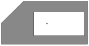
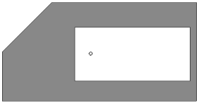
Variants of the placement of the center of mass of the flat face:
a) when the option Only outer contour is enabled,
b) when the option Only outer contour is disabled.
 By position and orientation
For post The swings of the attachment point indicate the point object that determines the position of the point, and the objects that determine the orientation of the axes.
Step-by-step instructions
1.Use one of the following methods to set the position of the attachment point:
•Select a point object. The name of the object is displayed in the field Point.
•To create a point, click the Create point  to the right of the field Point. Will start Subprocess of plotting a point.
A phantom attachment point appears in the graphics area.
2.Set the direction of the first axis (shown on the phantom as a segment with an arrow) in one of the ways:
•Select the object specifying the direction of the first axis. The object name will be displayed in the Axis 1 field.

•Build a vector by clicking Create vector  button to the right of the field Axis 1. Will start the process of vector construction.
The direction of the axis can be changed to the opposite by pressing the Change Direction button  to the right of the Axis 1 field.
3.Similarly, set the direction of the second axis (if the connecting point has two axes). The second axis is shown on the phantom with a segment without an arrow.
|
The guiding object for the second axis can specify a direction that is not perpendicular to the first axis. In this case, the direction of the second axis is defined as the projection of the direction that sets the object on a plane perpendicular to the first axis. An object cannot be used as a control for the second axis if it is parallel to the first axis or lies on the same straight line with it. A vector cannot be used as a guiding object for the second axis if it is parallel to the first axis. If an error is detected, a message is displayed. |