|
Building a Vector |
Scroll |
To begin building a vector, start by clicking Build Vector button  . Once you click it, buttons for activating vector-building commands will appear in the title toolbar of the Parameter Toolbar.
In KOMPAS-3D it is possible to construct:
•Vector by angle in the CS plane,
•Vector by two angles of spherical CS,
•Vector by edge or planar curve,
•Vector by cone axis or perpendicular to surface,
•Vector Perpendicular to Face at Specified Point,
•Vector perpendicular to the screen surface.
|
The Vector through two points command is active after launching the vector building process. |

After creating the vector, the system automatically returns to the command from which the vector building process was launched.
A vector directed from one point object to another is constructed using the Vector through two points  command.
After calling the command on the Parameter Toolbar, controls appear that allow you to set vector constructive parameters.
Step-by-step instructions
1.Pick first point object. The name of the selected point object is displayed in the field Starting point.
2.Pick the second point object. The name of the selected point object is displayed in the End point field.
Point features are specified in the graphics area or in the Design Tree. If necessary, you can build a point during the execution of the command. To do this, press the Build Point  button to the right of the Start Point(End Point) field. Will start subprocess of plotting a point. After creating the point, the system will return to the vector building process.
In the graphics area displays a vector phantom, directed from the first point to the second.
3.If necessary, the direction of the vector can be reversed (from the end point to the starting point) by clicking the Change direction  button.
4.To complete building the vector, click the Create object  .
.
Vector by angle in the CS plane
The vector directed at an angle to the specified coordinate axis and lying in the SC plane is constructed by the Vector by angle in the SC plane  command. After calling the command on the Parameter Toolbar, controls appear that allow you to set vector constructive parameters, and a vector phantom with default settings appears in the graphics area.
When constructing the vector plane is determined by the chosen axis:
•if the X axis is indicated, then the angle of the vector is counted in the XY plane,
•if the Y axis is indicated, then the angle of the vector is counted in the YZ plane,
•if the Z axis is indicated, then the angle of the vector is counted in the ZX plane.
Step-by-step instructions
1.Choose a coordinate system for constructing a vector from the list of SC. The list is available if there are several coordinate systems in the model. Otherwise, the vector is constructed in the absolute coordinate system of the model.
The starting point of the vector coincides with the beginning of the selected coordinate system.
2.Specify the axis of the coordinate system for reference angle vector. To do this, click the corresponding button in the Axis CS:
 From axis X in plane XY,
 From axis Y in plane YZ,
 From axis Z in plane ZX.
3.Set the angle of the vector to the axis in the field Angle.
The graphic region displays a vector phantom with the specified parameters.
4.If necessary, the direction of the vector can be reversed by clicking the Change direction button.
5.To complete the vector build, click the Create object button.
To build a vector directed along the specified CS axis, use the Vector by CS axis  .
.
After calling the command on the Parameter Toolbar, controls appear that allow you to set vector constructive parameters, and a vector phantom with default settings appears in the graphics area.
Step-by-step instructions
1.Choose a coordinate system for constructing a vector from the list of SC. The list is available if there are several coordinate systems in the model. Otherwise, the vector is constructed in the absolute coordinate system of the model.
The starting point of the vector coincides with the beginning of the selected coordinate system.
2.Specify the CS axis to set the direction of the vector by clicking the corresponding button in the group CS Axis:
 X Axis,
 Y Axis,
 ZAxis.
The graphic region displays a vector phantom with the specified parameters.
3.If necessary, the direction of the vector can be reversed by clicking the Change Direction button.
4.To complete the vector build, click the Create Object button.
To build a vector by coordinates, use the Vector by coordinates  command. Coordinates of a vector are expansion coefficients of that vector by coordinate axes X, Y, Z in the selected coordinate system.
After calling the command on the Parameter Toolbar, controls appear that allow you to set vector constructive parameters, and a vector phantom with default settings appears in the graphics area.
Step-by-step instructions
1.Choose a coordinate system for constructing a vector from the list of SC. The list is available if there are several coordinate systems in the model. Otherwise, the vector is constructed in the absolute coordinate system of the model.
The starting point of the vector coincides with the beginning of the selected coordinate system.
2.Enter the coordinates of the vector X, Y, Z in the Vector coordinates field.
The graphic region displays a vector phantom with the specified parameters.
3.If necessary, the direction of the vector can be reversed by clicking the Change direction button.
4.To complete building the vector, click the Create object button.
Vector by two angles of spherical CS
The vector, the direction of which in the chosen coordinate system is given by azimuth and spherical angles, is constructed by the Vector by two angles in the spherical coordinate system  command.
The direction of the vector is determined by two angles A and B. Angle A corresponds to the azimuth angle α spherical coordinate system, and the angle C – the zenith angle β. The origin of the spherical coordinate system coincides with the origin of the coordinate system of the vector. Azimuth angle α is counted in the XY plane of the vector coordinate system from the X axis counterclockwise (see figure below). In the XY plane, the OC beam is conducted at an azimuthal angle to the X axis.
In the plane passing through the Z axis and the OC half-line, the OD half-line is drawn at a zenith angle to the Z axis. This half-line determines the direction of the vector to be constructed.
|
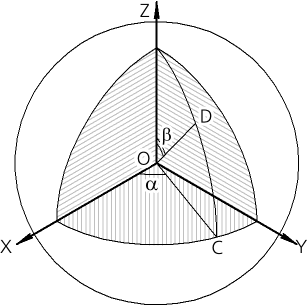
Determining the vector direction along the azimuth and zenith angles
After calling the command on the Parameter Toolbar, controls appear that allow you to set vector constructive parameters, and a vector phantom with default settings appears in the graphics area.
Step-by-step instructions
1.Choose a coordinate system for constructing a vector from the list of SC. The list is available if there are several coordinate systems in the model. Otherwise, the vector is constructed in the absolute coordinate system of the model.
The starting point of the vector coincides with the beginning of the selected coordinate system.
2.Enter the values of the azimuth and zenith angles A and B in the Coordinates field.
The graphic region displays a vector phantom with the specified parameters.
3.If necessary, the direction of the vector can be reversed by clicking the Change direction button.
4.To complete the vector build, click the Create object button.
Vector by edge or planar curve
The vector, the direction of which is set using a guide object – a straight-line object or a flat curve, is constructed by the Vector by edge or flat curve command.
When constructing a vector, any straight-line object or planar curve: a sketch line, an arc, a circle, an edge as an arc, as a circle or as an ellipse.
After calling the command on the Parameter Toolbar, controls appear that allow you to set vector constructive parameters.
Step-by-step instructions
1.Pick a guiding object in the graphics area or in the Design Tree. The name of the selected point object is displayed in the field Edge.
•If a straight edge or axis is selected as the guiding object, the vector is directed along the selected object.
•If a plane curve is chosen as a guiding object, then the vector is perpendicular to the plane of the curve.
The graphic region displays a vector phantom with the specified parameters.
2.If necessary, the direction of the vector can be reversed by clicking the Change direction button.
3.To complete the vector build, click the Create object button.
Vector by cone axis or perpendicular to surface
To build a vector, the direction of which is set using a guiding object – a flat object or a revolution surface, use the Vector along the axis of a cone or perpendicular to the plane command  .
.
As a guide can be used any flat object or any revolution surface, except a spherical one.
After calling the command on the Parameter Toolbar, controls appear that allow you to set vector constructive parameters.
Step-by-step instructions
1.Pick a guiding object in the graphics area or in the Design Tree. The name of the selected point object is displayed in the field Object.
•If a flat object is selected as a guiding object, then the vector is directed perpendicular to the selected object.
•If the surface of rotation is chosen as the guiding object, then the vector is directed along the axis of rotation.
The graphic region displays a vector phantom with the specified parameters.
2.If necessary, the direction of the vector can be reversed by clicking the Change direction button.
3.To complete building the vector, click the Create Object button.
Vector Perpendicular to Face at Specified Point
The vector passing through the specified point of the face and directed along the normal to the face at this point is constructed by the Vector Perpendicular to Face at Specified Point  command.
The position of the point is given by the displacement along the isoparametric curves U and V of theoretical surface of selected face.
After calling the command on the Parameter Toolbar, controls appear that allow you to set vector constructive parameters.
Step-by-step instructions
1.Specify the desired face in the graphics area.
A phantom of its theoretical surface and a vector phantom appear on the selected face. The phantom of the theoretical surface of the face is displayed as a grid of isoparametric curves U and V. The vector begins at the point where the face is specified and is perpendicular to it at that point.
The name of the selected face is displayed in the Surface. In UV Parameters field the values of the parameters U and V (in %) at the point of specifying the face are displayed.
2.Set the position of the initial point of the vector in one of the ways:
•Enter values for the U and V parameters in the field UV Parameters.
•Connect a point with a point object. To do this, activate the Snap point field and specify a point object. The name of the point object is displayed in the Snap Point field. The values of the parameters U and V in the UV parameter field are not available for editing.
The graphic region displays a vector phantom with the specified parameters.
3.If necessary, the direction of the vector can be reversed by clicking the Change Direction button.
4.To complete the vector build, click the Create object button.
To build a vector the direction of which is set by one of three basis vectors (t, n, and b) in a specified point of a curve are constructed using the Basis vector at a point of the curve  command.
The curve can be a spatial curve, a sketch line, an edge, or a broken line segment.
The position of the point and the corresponding three triples of basis vectors is given by the displacement along the curve some distance from its vertex. This point is the starting point of the created vector.
After calling the command on the Parameter Toolbar, controls appear that allow you to set vector constructive parameters.
Step-by-step instructions
1.Specify the curve to draw the vector in the graphics area or in the Design Tree. The name of the selected object is displayed in the field Curve.
Two phantoms will be created on the curve: a tangent vector and a starting vertex of the curve with an offset direction arrow (U). The tangent vector starts at the point where the curve is indicated.
2.Specify the position of the reference point of the basis vectors on the curve in one of the ways:
•Set the offset from the top of the curve by clicking the corresponding button in the group Move:
 In % of curve length: enter offset in percentages in the field% of curve length.
 By segment length: enter the offset in units of measurement of length in the field Length.
 By the central angle of the arc: enter offset in angular measurement units in the field Angle. (The option is available if an arc of a circle or ellipse is selected as the curve).
You can change the reference direction of the point offset to the opposite (from the final vertex of the curve to the initial one) by clicking the Change Direction  button to the right of the field where the offset value is set.
•Connect a point with a point object. To do this, activate the Snap point field and specify a point object. The name of the point object is displayed in the Snap Point field. In this case, the values of the parameters in the group Move are not editable.
3.Select the direction of the vector relative to the curve by clicking the corresponding button in the Vector group:
 Tangential,
 Of Principal Normal,
 Binormals.
The graphic region displays a vector phantom with the specified parameters.
4.If necessary, the direction of the vector can be reversed by clicking the Change direction button.
5.To complete building the vector, click the Create object button.
Vector perpendicular to screen surface
To build a vector perpendicular to the screen plane, use the Vector perpendicular to screen surface  command.
After calling the command on the Parameter Toolbar, controls appear that allow you to set vector construction parameters, and a vector phantom is displayed in the graphics area in the center of the screen, directed to the observer.
Step-by-step instructions
1.Set the position of the vector in space relative to the model using the Fix position option.
If this option is enabled, then when changing the orientation of the model, the vector rotates with the model. If necessary, you can change the position of the model without changing the position of the vector. To do this, disable the option. The vector is located in the center of the screen and is directed perpendicular to the screen plane.
2.If necessary, the direction of the construction of the vector can be reversed by clicking Change direction .
3.To complete the build, click Create object .