|
Profile |
Scroll |
The profile parameters of the strengthening edge are configured in the Profile group of elements.
Methods of plotting
You can select a profile construction method using the Method group of buttons. The following options are available.
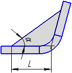
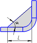
 By side and angle – the length of the first side of the profile and the angle of inclination of the profile to this side are specified in the fields Length 1 and Angle.
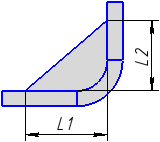
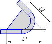
 By two sides — the lengths of the first and second sides of the profile are specified in the fields Length 1 and Length 2.
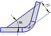
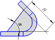
 By depth and angle — the profile depth and the profile angle of inclination to the first side are specified in the fields Depth and Angle.
The slope angle of the profile may take values from 0° to 90°.
By default, the first side of the profile is the side which intersects the specified bend edge. If you need to change the side, click the Change Direction  button to the right of the Length 1 field (for methods By Side and Angle and By Two Sides) or Angle (for the method By Depth and Angle).
The profile parameters are measured in the plane perpendicular to the selected bend edge.
In the process of building, you can switch between profile design methods. The parameter values will be recalculated and displayed in the fields corresponding to the selected method.
Drawing schemes of the strengthening edge profile are given in the Table.
Drawing schemes of the strengthening edge profile
Method |
Bend angle from 0° to 90° |
Bend angle 90° |
Bend angle from 90° to 180° |
|
|
By side and angle |
|
|
|
|
By two sides |
|
|
|
|
By depth and angle |
|
|
|


A strengthening edge profile can be straight or with bulge.
|
|
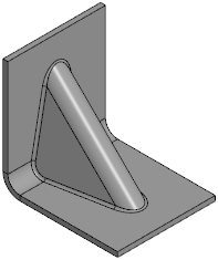
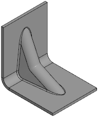
Examples of strengthening edge profiles: straight and with bulge
To generate a bulge, do the following operations.
1.Set the Bulge toggle switch to position I (enabled).
2.Select a method to specify the bulge depth and specify a parameter for the selected method. The depth is determined by the distance from the point of intersection of the bend angle with the original contour of the profile to the bottom point of the bulge (see figure below).
The method to specify depth is selected using the Parameter control group:
 % max. depth – in the field Depth, % specifies the maximum depth in percentage,
 Distance — set the depth in the Depth field in units of length measurement.
In the process of plotting, you can switch between methods of setting the bulge depth. The value will be recalculated and displayed in measurement units according to the selected method.
3.In the Bulge radius field, set the radius. The minimum value of bulge radius is 0.
Bulge parameters are measure in the plane perpendicular to the edge of the bend on which the strengthening edge is being created. The scheme of plotting the bulge is shown in the figure.
|
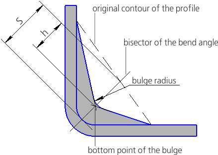
Scheme for constructing a bulge on a strengthening edge
The depth h is calculated by equation:
h = k · S / 100,
where k is depth of the bulge as percentage.
|
Parameters and shape of bulge are shown conditionally in the scheme. The surface of strengthening edge with bulge has spline shape, the most close to the specified. |
