|
Position of the Strengthening Edge |
Scroll |
The strengthening edge is located in such a way so that its median plane (a bisector plane of the dihedral angle formed by side faces of the element) is located perpendicular to the rectilinear edge of the bend.
To set the position of the strengthening edge, you have to specify at which point its median plane intersects the edge of the bend. You can do this using one of the following methods:
•by shifting from the vertex of the edge bend,
|
|
a) |
b) |
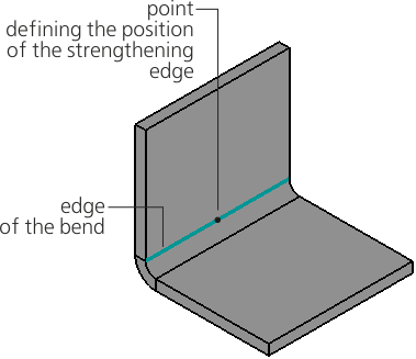
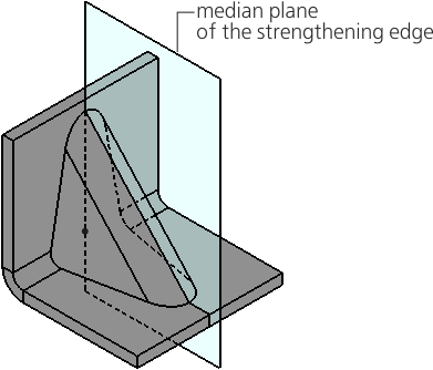
Placement of a strengthening edge on the bend edge:
a) indication of the position of the strengthening edge, b) construction result
A rectilinear bend edge is automatically defined after the bend is specified. The name of the edge is displayed in the Bend Edge field on the Parameters bar.
If required, you can change the bend edge. To do this, specify a different rectilinear edge in the graphics area.
Offset defines the position of the median plane of the strengthening edge relative to the start vertex of the bend edge.
You can select an offset method using the Move group of buttons.
 In % of the curve length — the offset in percent is specified in the field % of curve length,
 By segment length — the offset in units of length measurement is set in the Length field.
The starting vertex of the edge is marked with a green arrow on the phantom of the element. The vertex can be changed by clicking the Change Direction  button to the right of the offset value input field.
The position of the median plane of the strengthening edge can be defined by the existing point object.
To specify an object, click in the Snap Point field. Then, in the Design tree or in the graphics area, specify a point object which will project onto the bend edge.
You can build a point during the command execution. To do this, click the Construct Point  button located to the right of the Snap Point field. Will start Subprocess of plotting a point.
The name of the point object is displayed in the Snap Point field. In this case, the field to enter an offset value is not available for editing.
An associative relation is automatically generated between the strengthening edge and the selected point object or specially built point. Due to this associativity, the strengthening edge will follow the object when its position changes.
To remove associativity, click "x" in the Snap Point field. The field will be cleared. The median plane of the strengthening edge will pass through the point object but will be no longer associated with it.