|
Types of face extension |
Scroll |
To select a face extension type, use the corresponding button in the Extension type group and specify the required parameters, see the table.
Extension types
Extension type |
Result of plotting |
|
|
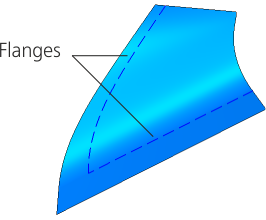
Extension of edges is performed without adding new edges — edges are extended beyond the open edges along their theoretical surface. Assign position of the lateral edges extension. The edge of the extended surface is equidistant from the edge of the original surface. If necessary, enable the option Type of face extension. If needed, split into faces the extended surface. If the surface to be extended is not analytical (see application Parametric surface representation. Isoparametric curves), then it is impossible to build an extension section with the same surface area. n this case, within the framework of this method, the construction is performed By tangent, but without creating new edge. |
|
|
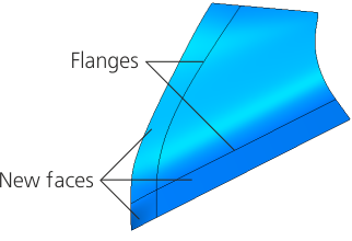
By tangent Extension is made by creating new faces which are tangent to the source faces along the selected edges. Specify the position of the lateral edges of extension. If plotting By tangent resulted in an element which is an extension of the surface being extended, (that is, the plotting result is no different from extension By the same surface), then the new face is merged with the source face. |
|
|
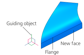
Surface extension is performed by creating new faces formed by moving the selected flanges in the specified direction. Specify the direction of extending the faces. |
|


Position of the lateral edges of the extension
If the Extension type group of elements specifies the edge extension option By the same surface or By tangent, the Parameters panel will make available a group of elements Side edges.
Select the position of lateral edges of extension using the corresponding button:
 As extension of original lateral edges,
 By normal to specified borders.
Possible positions of lateral edges are shown on the picture below. The edge with the face extended beyond it is shown with a dashed line.
|
|
|
a) |
b) |
c) |
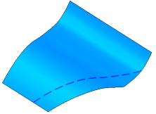
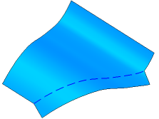
Possible position of lateral edges
a) original object, b) extension of initial lateral edges,
c) extension by normal to specified flanges
Direction of extending the faces
If the Extension type group of controls has the By direction method selected, the flanges of the faces are moved in the specified direction.
You can use any straight-line or planar object as a guiding object. Straight–line and flat objects are listed in the table.
•Direction set by a straight — line object is a straight line parallel to the object.
•The direction specified by a flat object is a straight line perpendicular to the object.
In addition, guiding object can be a vector.
Specify a guide object in the graphics area or Design tree, or construct a vector. The name of the selected object will be displayed in the Direction field.
To construct a vector, click the Create vector  button to the right of Direction. The process of building vector will launch. Perform the necessary steps for construction and click the Create object button. The system will return to the surface extension operation, and the created vector will be automatically selected as the guide object.
The direction of edge extension can be reversed by pressing the Change direction button to the right of the field Length. The field is available if the option For specified length is selected in the Method group.
Surface extension with edge simplification
You can extend the surface beyond the limits of the existing extension algorithm in cases where the length is limited by the degeneration of the equidistant edge, or when the equidistant edge no longer intersects with the extensions of the side edges. The Edge simplification option is used for this purpose. This option is available on the Parameters panel if the By the same surface option is selected in the Extension type group.
•When this option is disabled, the surface is not extended.
•When this option is enabled, the surface is extended to the specified length. The simplified edge is not exactly equidistant from the edge of the original surface. The distance between the simplified edge and the edge of the original surface may not coincide with the distance specified by the user at all point.
The figure shows an example of surface extension without simplification and with edge simplification.
|
|
a) |
b) |
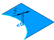
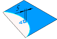
Extension of the surface to a distance at which the equidistant edge
does not intersect with the continuation of the side edge:
a) When the Edge simplification option is disabled, this is not possible.,
b) with the option enabled Edge simplification
Splitting to edges on edges of extended surface
You can split the extended surface at the edge. The option Split to edges. The option is available on the Parameters panel if the group of elements Extension type of faces variant is By the same surface,and in group Result the button is pressed Source surface  . When this option is enabled, the extended surface is split into the original surface and the extended section, i.e., an edge is created that separates the original and new parts of the surface.