|
Angular dimension from Common Datum |
Scroll |
Angular dimension from datum combined is a group of simple angular dimensions with the first sides of angles coinciding and dimension text located in a special way.
Parameters are set separately for each dimension in the group. If all dimensions must have the same parameters (e.g. arrows of a certain type), call the Remember setting command from the button menu  in the header of the Parameters Panel. You will see a tick mark next to the command name, and selected parameters will be stored for subsequent dimensions.
Dimensions included in the group are independent objects. They can be selected, edited and removed separately.
To create a group of angular dimensions with a common dimension line, do the following.
1.Invoke the Angular from Common Datum command  .
.

2.Set the first and second sides of the angle to set the first dimension in the group. To do this, specify rectilinear objects or points in the graphic area that can be joined to create angle sides (see section Angle sides configuration).
The graphic area will display the angle vertex and dimension phantom.
3.Select the type of the first dimension using the Type group of buttons:
 Minimum angle — dimensioning the acute angle,
 Maximum Angle — dimensioning the obtuse angle,
 Angle greater than 180 degrees — dimensioning an angle of greater than 180 degrees.
|
You can only select the type for the first dimension in the group before it is fixed. The type is system-defined for all the other group dimensions. You cannot change it. |

4.Select how dimension’s extension lines are to be drawn using the Leader lines group of buttons:
 Not from center,
 From the center.
5.Edit the dimension text, if required. To start working with the dimension text, press any alphanumeric key. See section on editing the dimension label...
6.Set the number of decimal places in the dimension text. Details...
7.Set a dimension tolerance. Details...
8.Set up additional dimension parameters, if required: arrow display parameters, etc. Details...
9.Set the point defining the dimensional line location. This position will be the same for all dimensions in the group.
10.Specify a sequence of second sides of the angles for the rest of dimensions in the group. Configure dimension parameters, if required. You can configure a dimension until the angle’s second side is specified.
|
All specified angle sides must go through the same point – vertex of the first angle. If points are used to set sides, after you set the first side of the angle, coordinates of its vertex are stored by the system. To set the second side, you only need to specify a point on this side – it will go through this point and the vertex. If sides are set using segments, the angle vertex coordinates are not stored in the system. The second segment must be positioned so that it (or its extension) goes through the angle vertex. |
|
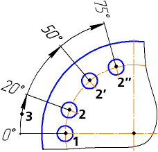
Setting angular dimensions from datum combined
(angle sides set using points)
11.If you want to switch to setting the next dimension group, cancel selection of the angle’s first side. Press the Start new input  button or delete the name of the selected segment from the Objects field.
12.To complete operation of the command, click Finish  .
.
See Also