|
Constraints designation in the graphic area |
Scroll |
The constraints of all objects are displayed in the graphic area when enabled constraint display mode. With the mode disabled, only the constraints of the selected object can be seen if the setup dialog The Display restriction icons for selected objects option is enabled.
For designating constraints in the graphic area, special icons are used. For some constraints, additional elements are also displayed — dashed lines, crosses, etc. The designations of constraints are provided in the table.
Constraint |
Example |
Comments |
|
|
Horizontality |
|
|
|
Verticality |
|
|
|
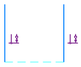
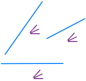
Alignment horizontal |
|
Hatched horizontal segment connecting the aligned points |
|
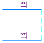
Alignment vertical |
|
Hatched horizontal segment connecting the aligned points |
|
Point Coincidence |
|
A location of the point coincidence is marked with a circle. |
|
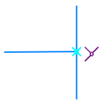
Point on curve |
|
The location of the point on the curve is marked with a cross. If necessary, the curve is extended with a dashed line. |
|
Curve midpoint |
|
A location of the curve midpoint is marked with a crosshair. |
|
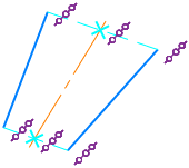
Symmetry of Points |
|
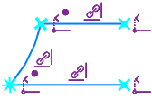
An additional dashed segment is shown, which joins the symmetrical points, and a square at the intersection of the segment with the symmetry axis. If necessary, the axis is extended with a dashed line to the square center. |
|
Three points at right line |
|
Additional segments are displayed, joining the points on the same straight line. Intersections of those segments with the centerline are marked by crosses. The constraint is created automatically when constructing a centerline by the Auto Centerline. |
|
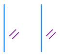
Parallel |
|
|
|
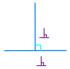
Perpendicular |
|
An additional icon of right angle is shown at the intersection of objects. If necessary, the objects are extended with a dashed line |
|
Collinear |
|
An additional dashed line is shown, joining the closest ends of segments. |
|
Bisector |
|
|
|
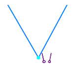
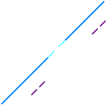
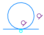
Tangency |
|
The tangency point is marked by a special icon. If necessary, the curves are extended up to the tangent point with a dashed line. |
|
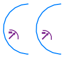
Equal Radius |
|
|
|
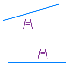
Equal Length |
|
|
|
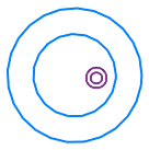
Concentricity |
|
An icon is placed near the center of concentric objects |
|
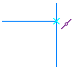
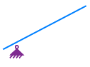
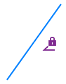
Fixed Point |
|
An icon is placed near a fixed point |
|
Fixed length |
|
|
|
Fixed angle |
|
|
|
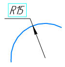
Fixed size |
|
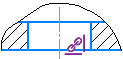
A rectangular frame is displayed around the dimension value. The constraint icon is not shown in the graphics area. If the dimension has a variable, it is shown in parentheses below the dimension value (for more details, see the section Notes of displaying dimensions with variables). |
|
Projection link End vertex projection |
|
Icon Projection link is shown in the sketch next to the projection objects (curves, points), and the icon End vertex projection— near the extreme points of the projection curves, if they are open. For information on projecting objects, see the section Projection mode objects to a sketch. |
|
Projection |
|
The icon is shown in the drawing next to projection designations. |
|
Array by grid |
|
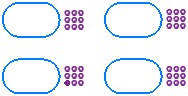
The Array by grid icon is displayed next to each object in a parallelogram grid array. |
|
for the source object for a copy object |
||
|
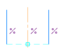
Array by concentric grid |
|
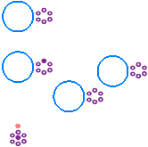
The icon Array by concentric grid is shown next to each object in the array in a concentric grid and next to the center point of the array. |
|
for the source object for a copy object for the center point of the array |


See Also