|
Setting the surface width |
Scroll |
The width of the fillet surface is determined by the points of contact between the section and the original surfaces (the sets of contact points form the boundaries of the fillet surface). There are several ways to define the contact points, i.e., to specify the surface width. The Width group elements are used to select the width definition method. Full fillet on the Parameters Panel. A description of the methods and examples of creating rounded surface boundaries are provided in the table.
Methods for specifying the width of a fillet surface
|
Way |
Example |
|
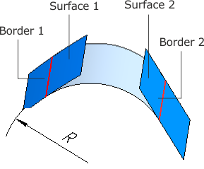
Along the radius of the inscribed circle During construction, the points of contact between the ends of an arc of a given radius (R) and the original surfaces are determined at each section position. The radius at various section positions is calculated using a function whose type is selected using the Function Type group of buttons. Specify the function type and set the appropriate parameters.
More about defining the function of modifying a parameter... |
|
|
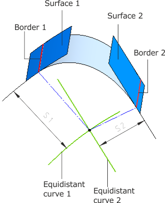
When constructing a section, the points closest to the intersection point of curves equidistant from the intersection curves of the section plane and the original surfaces are found at each section position. The position of the equidistant curve is determined by the offset from the specified surface (S1 and S2, respectively). Offsets at different section positions are calculated according to specified functions. A different function type is selected for each side. This is accomplished using groups of buttons.Function Type over the fields Offset 1 and Offset 2. Select the function type and set the appropriate parameters.
|
|
|
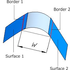
When constructing a cross-section, points are defined on the reference surfaces at each cross-section position, and the distance between these points is equal to the chord width (W). The chord width at various cross-section positions is calculated using a function whose type is selected via the Function Type button group located below the Width group. Specify the function type and set the corresponding parameters.
|
|
|
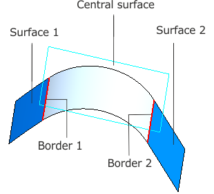
At each point of the cross-section, an arc is constructed that is tangent to the original surfaces and the central surface. The central surface may be chosen as: •a face of a surface or a solid, •a set of faces that are tangent to one another, •an auxiliary or coordinate plane. Specify a surface. Its name appears in the Central surface field. To the right of the field is the Change Direction button. |
|
|
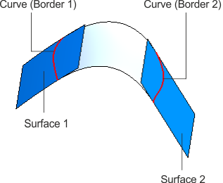
The boundaries of the fillet surface are defined by curves lying on the original surfaces. The following can be used as a boundary curve: •a curve or a chain of curves, •an edge or a chain of edges. If the curve consists of a chain of objects, they must be joined along the tangent. Specify the curves. The curve names are displayed in the fields Curve 1 and Curve 2. |
|

 Constant
  Linear
 Cubic
Cubic 




 . This feature allows you to reverse the direction of the construction relative to the normal of a given surface.