|
Methods of constructing a surface |
Scroll |
When drawing a rounding surface, the «rolling the ball»method and the method of flat section movement along the orienting line are used.
If at least one of the operation parameters is determined by a variable function type, then a guiding line is used to construct the surface. It is used to set the range of parameter changes, i.e. to determine where its initial value is and where its final value is. In the method of "rolling the ball", the defining line must be specified, and in the method of movement of a flat section, such a line is the orientation line.
For successful construction, it is recommended to choose the defining line so that its beginning and end are located at the level of the beginning and end of the curve of intersection of the original surfaces or their equidistant surfaces.
To set the way to build the rounding surface, click the corresponding button in the Section motion group in the Design section on the Parameters Panel.
 Autodetection (default method) — the rounding surface is formed by «rolling the ball» between these surfaces. The plane of section of the rounding surface passes through the center of the ball and its points of contact with the original surfaces.
In cases where a function with non-constant parameters is used to specify the width of the rounding surface, you must specify a defining line that defines the beginning and end of the range of variation of the parameter. A curve or a chain of curves can be specified as a defining line. The Defining line field is displayed in the Parameters panel, which contains the name of the specified object.
For successful construction, it is recommended to choose the defining line so that its beginning and end are placed at the level of the beginning and end of the curve of intersection of the initial surfaces or their equidistant surfaces.
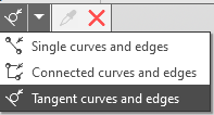
More about curve selection based on conditions...
The names of the selected objects are shown in the Guiding line field.
 Along the line — The rounding surface is formed by the movement of a flat section along a given orientation line: at each point of the orientation line, the section plane is perpendicular to it. A curve or a chain of curves can be specified as an orientation line.
For one indication in the graphical area, you can select one curve or several curves that satisfy a certain condition. The elements of the Quick Access Toolbar are used to set the condition (see the picture above).
The names of the selected objects are displayed in the Guide line field on the Parameters Panel. For more information, see the section Line mothion in the description of the conic section surface.
For successful construction, it is recommended that a curve be chosen as the orienting line, at each point of which the planes perpendicular to it will have a predictable intersection with both the first and second specified surfaces.
In cases where, during the task width and/or form of the rounding surface, at least one of the parameters is set by a variable function type, and the orientation line acts as a guiding line.
After specifying the desired construction method, a phantom of the rounding surface with default parameters appears on the screen. The direction of the surface construction (green arrow on the phantom) can be reversed by pressing the button Change direction  under the field Guiding line (Guide line).
