|
Constructing a chamfer |
Scroll |
To construct a chamfer, use the Chamfer  .
.

Step-by-step instructions
1.Specify an edge (edges) in the graphic area to construct a chamfer.
If you want to build a chamfer on all edges of a face, then you can specify the face itself. One object or group of objects satisfying a certain condition is selected for one indication. The elements of the Quick Access Toolbar are used to set the condition.
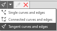
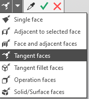
The names of the selected objects are displayed in the Objects field in the Main section of the Options Panel.
After specifying the first edge, the graphic area displays the phantom – an arrow directed along one of the faces. The arrow indicates the direction to build the first side of the chamfer. The chamfer angle will be measured relative to the same direction.
|
The command is not executed for edges formed by smoothly conjugate faces. |

1.Select the chamfer design method by clicking the desired button in the Method group and specify the parameters:
 By side and angle — set the length of the first side of the chamfer in the field Length 1. Enter the angle value in the field Angle.
 By two sides — set the lengths of the first and second side of the chamfer in the fields Length 1 and Length 2.
2.The direction of constructing the first side of the chamfer can be changed to the opposite by clicking Change Direction to the right of the Length 1 field.
3.If necessary, set the name of the chamfer and its surface properties in the Properties section. More details on the management of the color and optical properties....
4.To complete the operation, click Create Object  .
.
5.After confirming completion of the operation, a chamfer appears on the model edges and a corresponding icon .
6.To complete the command, click Finish  .
.
Tips
•The values of side lengths and the chamfer angle can be set in the graphics area – using characteristic points (for characteristic points, see Defining Points of Objects).
•You can set linear and angular parameters using the geometrical calculator.
•You may assign tolerances, specified in linear or angular units, to operation parameter values. To do this, you should select the Tolerance command located in the menu of the required parameter, or click the icon displayed in the parameter field (the icon is displayed if a tolerance is assigned to the parameter value). More details on assigning tolerance...
